9
vacon • 76 CONTROL KEYPAD
Tel. +358 (0) 201 2121 • Fax +358 (0)201 212 205
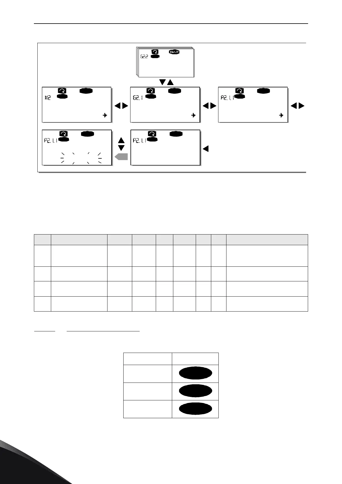
Figure 46. Parameter value change procedure
9.3.3 Keypad control menu (M3)
In the
Keypad Controls Menu
, you can choose the control place, edit the frequency reference and
change the direction of the motor. Enter the submenu level with the
Menu button right
.
9.3.3.1 Selection of control place
There are three different places (sources) which the frequency converter can be controlled from.
For each control place, a different symbol will appear on the alphanumeric display:
Change the control place by entering the edit mode with the
Menu button right
. The options can then
be browsed through with the
Browser buttons
. Select the desired control place with the
Enter
button
. See the diagram on the next page. See also 9.3.3 above.
Table 25. Keypad control parameters, M3
Code Parameter Min Max Unit Default Cust ID Note
P3.1 Control place 1 3 1 125
1 = I/O terminal
2 = Keypad
3 = Fieldbus
R3.2 Keypad reference Par. 2.1.1
Par.
2.1.2
Hz
P3.3 Direction (on keypad) 0 1 0 123
0 = Forward
1 = Reverse
R3.4 Stop button 0 1 1 114
0 = Limited function of Stop button
1 = Stop button always enabled
Control place symbol
I/O terminals
Keypad (panel)
Fieldbus
G1
G8
READY
Keypad
P1
P18
READY
Keypad
13.95 Hz
READY
Ke ypad
G1
G8
Keypad
READ Y
Keypad
13.95 Hz
enter
READ Y
Ke ypad
14.45 Hz
Parameters Basic parameters Min Frequency
Input signals
Min Frequency Min Frequency
11529_uk