Do you have a question about the Vacon nxs and is the answer not in the manual?
| Model | Vacon NXS |
|---|---|
| Humidity | 5% to 95% non-condensing |
| Standards | CE |
| Storage Temperature | -40 to 70 °C |
| Protection Class | IP54 |
Describes the manual's purpose and scope.
Details compliance with EC standards for the AC drive.
Confirms the drive's compliance with Underwriters Laboratories standards.
Certifies compliance with Australian Radio Communications Agency standards.
Explains the meaning of safety symbols used throughout the manual.
Provides critical warnings about electrical hazards and safe handling.
Offers cautions to prevent damage to the drive or system.
Details requirements for proper grounding for safety.
Specifies EMC requirements and compliance standards.
Guidance on using residual current devices for protection.
Information on how to read and verify the product's package label.
Explains the structure and meaning of the drive's type designation code.
Instructions for proper storage conditions to maintain drive integrity.
Steps for safely unpacking and handling the AC drive.
Provides the weight specifications for different drive frames.
Lists and describes available accessories for the AC drives.
Details the cable accessories included for FR4-FR6 frames.
Details the cable accessories included for FR7-FR8 frames.
Describes the purpose and use of the product modification label.
Guidelines for the environmentally sound disposal of the AC drive.
Provides general guidelines and considerations for mounting the AC drive.
Details the dimensions required for wall-mounting the drives.
Specific dimensions for wall mounting FR4 to FR6 frames.
Specific dimensions for wall mounting FR7 frames.
Specific dimensions for wall mounting FR8 frames.
Specific dimensions for wall mounting FR9 frames.
Details the dimensions required for flange mounting the drives.
Specific dimensions for flange mounting FR4 to FR6 frames.
Specific dimensions for flange mounting FR7 and FR8 frames.
Specific dimensions for flange mounting FR9 frames.
Provides dimensions for standalone drive installations.
Specific dimensions for FR10 and FR11 standalone drives.
Information on cooling requirements and air flow for the drives.
Cooling requirements specific to FR4 to FR9 frames.
Cooling requirements for FR10-FR11 standalone units.
Instructions for connecting mains and motor cables to the drive.
Requirements for cabling according to UL standards.
Guidance on selecting appropriate cable and fuse sizes.
Tables detailing cable and fuse sizes for specific voltage and frame ranges.
Tables detailing cable and fuse sizes for specific voltage and frame ranges.
Tables detailing cable and fuse sizes for specific voltage and frame ranges.
Tables detailing cable and fuse sizes for specific voltage and frame ranges.
Explanation of the drive's power unit connection topology.
Information on connecting brake resistor cables.
Steps to take before installing cables.
General procedures for installing cables.
Specific cable installation steps for FR4 to FR7 frames.
Description of the components that make up the control unit.
Instructions for wiring the control unit.
Guidance on selecting appropriate control cables.
Details of the terminals on the control unit's I/O and relay boards.
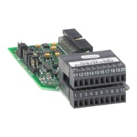
Instructions for installing optional expansion boards.
Explanation of the galvanic isolation barriers used in the drive.
Description of the control keypad buttons and their functions.
Explanation of the drive status and control place indicators on the display.
How to navigate through menus and submenus on the control panel.
How to monitor drive parameters and signals.
Instructions for accessing and modifying drive parameters.
Steps to locate specific parameters within the menu structure.
Procedure for editing parameters that have text-based values.
Procedure for editing parameters with numerical values.
Menu for controlling drive functions via the keypad.
Explanation of the different control places for the AC drive.
Submenu for setting the keypad reference value.
How to change the motor's rotation direction using the keypad.
Instructions for disabling the stop motor function.
Details on special functions available in the keypad menu.
How to view active faults detected by the drive.
Information on accessing recorded data at the time of a fault.
How to view the history of past faults.
Menu for system-wide settings and information.
Procedure for changing the control panel's display language.
How to select and change the drive's application.
Function to copy parameters between drives or save/load sets.
How to compare current parameter values with saved sets.
Settings related to drive security and access control.
Instructions for setting and managing the drive's password.
How to lock parameters to prevent unauthorized changes.
Guides through initial drive setup and configuration.
Settings for simultaneously monitoring multiple drive values.
Configuration options for the control panel's keypad behavior.
Setting the default screen shown after a timeout or power-up.
Setting the default screen for the operating menu.
Configuring the time before the display returns to the default page.
Adjusting the display contrast for better readability.
Setting the duration for the keypad backlight.
Configuration options related to the drive's hardware components.
Setting for the internal brake resistor connection status.
Configuring the operation mode of the cooling fan.
Setting the timeout for HMI acknowledgements.
Setting the number of retries for HMI acknowledgements.
Configuration for using a sine filter with the drive.
Setting for controlling the pre-charge mode.
Information about the drive's hardware, software, and operation.
Displays total operation counters like MWh and hours.
Information on resettable counters for drive trips.
Details on the drive's software version and package.
Information about the applications installed on the drive.
Information on the drive's hardware components.
Information on connected expander boards.
Menu for managing expander board parameters.
Additional application-related functions for the keypad.
Essential safety precautions before starting drive commissioning.
Step-by-step guide for commissioning the AC drive.
Procedures for operating the motor safely.
Pre-operation checks to ensure safe motor startup.
Performing run tests without the motor connected for safety.
Steps for conducting initial start-up tests safely.
Procedure for tuning motor and drive parameters.
Steps for connecting the motor to the operational process.
Performing insulation resistance tests on cables and motor.
Specific installation requirements for IT systems regarding EMC.
IT system installation steps for FR4, FR5, and FR6.
IT system installation steps for FR7.
IT system installation for FR8 to FR11.
Information on regular maintenance tasks for the drive.
Procedure for reforming capacitors after long storage.
Specifications of AC drive power ratings across various models.
Power ratings for drives operating at 208-240V mains voltage.
Power ratings for drives operating at 380-500V mains voltage.
Power ratings for drives operating at 500-690V mains voltage.
Details on the drive's low and high overload performance.
Specifications for brake resistor ratings.
General technical data for NXS and NXP AC drives.
Information on the drive's compliance with EMC standards.
Definitions of environments for EMC standard compliance.
Procedures for resetting faults on the AC drive.
A comprehensive list of fault codes, causes, and solutions.
Graphs showing power loss versus switching frequency for 380-500V.
Graphs showing power loss versus switching frequency for 500-690V.