Descriptions of VACON® option boards vacon • 19
Local contacts: http://drives.danfoss.com/danfoss-drives/local-contacts/
3
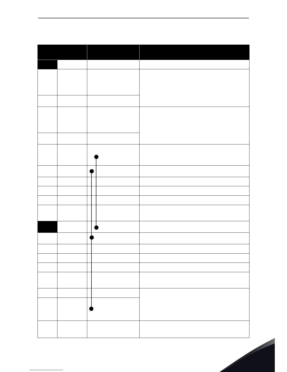
I/O terminals on OPTA1 (coded terminals painted black)
Table 5. OPTA1 I/O terminals
Terminal
Parameter reference
on keypad and NCDrive
Technical information
1
+10 Vref Reference output +10V; Maximum current 10 mA
2
AI1+ An.IN:A.1
Selection V or mA with jumper block X1 (see page 20):
Default: 0– +10V (Ri = 200 kΩ)
(-10V..+10V Joy-stick control, selected with ajumper)
0– 20mA (Ri = 250 Ω)
Resolution 0.1%; Accuracy ±1%
3
AI1–
Differential input if not connected to ground;
Allows ±20V differential mode voltage to GND
4
AI2+ An.IN:A.2
Selection V or mA with jumper block X2 (see page 20):
Default: 0– 20mA (Ri = 250 Ω)
0– +10V (Ri = 200 kΩ)
(-10V..+10V Joy-stick control, selected with a jumper)
Resolution: 0.1%; Accuracy ±1%
5
AI2–
Differential input if not connected to ground;
Allows ±20V differential mode voltage to GND
6
24 Vout (bi-
directional)
24V auxiliary voltage output. Short-circuit protected.
±15%, maximum current 150 mA, see 1.4.4.
+24Vdc external supply may be connected.
Galvanically connected to terminal #12.
7
GND
Ground for reference and controls
Galvanically connected to terminals #13,19.
8
DIN1 DigIN:A.1
Digital input 1 (Common CMA); R
i
= min. 5kΩ
9
DIN2 DigIN:A.2
Digital input 2 (Common CMA); R
i
= min. 5kΩ
10
DIN3 DigIN:A.3
Digital input 3 (Common CMA); R
i
= min. 5kΩ
11
CMA
Digital input common A for DIN1, DIN2 and DIN3.
Connection by default to GND.
Selection with jumper block X3 (see page 20):
12
24 Vout (bi-
directional)
Same as terminal #6
Galvanically connected to terminal #6.
13
GND
Same as terminal #7
Galvanically connected to terminals #7 and 19
14
DIN4 DigIN:A.4
Digital input 4 (Common CMB); R
i
= min. 5kΩ
15
DIN5 DigIN:A.5
Digital input 5 (Common CMB); R
i
= min. 5kΩ
16
DIN6 DigIN:A.6
Digital input 6 (Common CMB); R
i
= min. 5kΩ
17
CMB
Digital input common B for DIN4, DIN5 and DIN6.
Connection by default to GND.
Selection with jumper block X3 (see page 20):
18
AO1+ AnOUT:A.1
Analogue output
Output signal range:
Current 0(4)–20mA, R
L
max 500Ω or
Voltage 0—10V, R
L
>1kΩ
Selection with jumper block X6 (see page 20):
Resolution: 0.1% (10 bits); Accuracy ±2%
19
AO1–
20
DO1 DigOUT:A.1
Open collector output
Maximum U
in
= 48VDC
Maximum current = 50 mA