Descriptions of VACON® option boards vacon • 25
Local contacts: http://drives.danfoss.com/danfoss-drives/local-contacts/
3
Technical data:
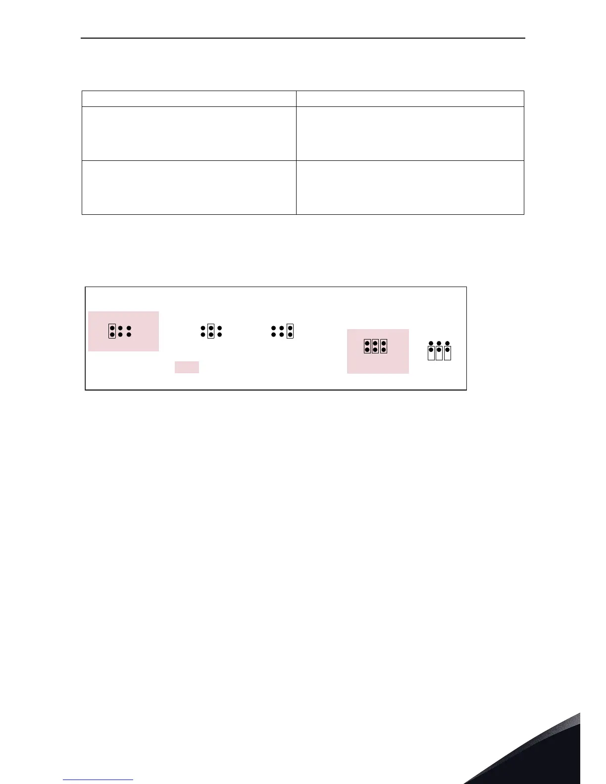
Jumper selections
On the OPTA4 board, there are two jumper blocks. The jumper X2 is used to define the status of the
termination resistor (R=135Ω). The jumper X4 is used to program the control voltage (auxiliary
voltage). The factory default and other available jumper selections are presented below.
Encoder control voltage, +5V/+15V/+24V Control voltage selectable with jumper X4.
Encoder input connections,
inputs A+, A–, B+, B–, Z+, Z–
Max. input frequency ≤150kHz
Inputs A, B and Z are differential
Encoder inputs are RS-422 interface compatible
Max. load per encoder input I
low
= I
high
≈ 25mA
Qualifier input ENC1Q
Fast digital input DIC4
Max. input frequency ≤10kHz
Min. pulse length 50μs
Digital input 24V; R
i
>5kΩ
Digital input is single-ended; connected to GND
2:
Te r m i n a t i o n r e s i st o r
Termination resistor
used
Termination resistor
not used
5V
15V
24V
=
Fa cto r y d ef a u lt
5V
15V
24V
5V
15V
24V
Jumper block X 4 :
Auxiliary voltage level
Auxiliary voltage +15V Auxiliary voltage +24VAuxiliary voltage +5V
7247.emf
NOTE: If one encoder is connected to one
drive only, the termination resistor on the
board must be used. If the encoder is con-
nected to several drives, the termination
resistor of the last drive must be used.