8000026412_01 Air/flue pipe installation manual 43
5.17 Installing the flue gas pipe on the external
wall
To install the flue gas pipe on the external wall, you must first
drill the hole in the external wall and install the external wall
console. Then install the line on the external wall and the
horizontal section with the unit connection.
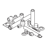
5.17.1 Scope of delivery of basic elements for
external wall installation – 0020042748
1 Inspection elbow,
80/125 mm diameter
2 70 mm air pipe clamp
(2 pcs)
3 Extension 0.5 m,
80/125 mm diameter
4 Split collar (outside),
stainless steel
5 Collar (internal)
6 Wall duct elbow 87°,
80/125 mm diameter,
stainless steel
7 Stainless steel air pipe
clamp (2 pcs)
8 Terminal piece, stain-
less steel
9 Air intake piece, stain-
less steel
5.17.2 Scope of delivery of basic elements for
external wall installation – 0010039735
1 70 mm air pipe clamp
(2 pcs)
2 Wall duct elbow 87°,
80/125 mm diameter,
stainless steel
3 Air intake piece, stain-
less steel
4 Terminal piece, stain-
less steel
5 Stainless steel air pipe
clamp (2 pcs)
6 Divided collar, stainless
steel (2 pcs)
7 Inspection elbow,
80/125 mm diameter
5.17.3 Observing the static dimensions
Before starting the installation, determine the route of the
flue system and the number and position of the wall consoles
and external wall pipe brackets.
Danger!
Risk of injury due to falling parts.
Exceeding the static dimensions may lead
to mechanical damage to the flue system. In
extreme cases, parts may become loose from
the wall and fall, thus endangering persons.
▶ During installation, observe the static di-
mensions.
▶ Secure at least every second extension to
the external wall using a pipe clamp.
▶ On façades with thermal insulation com-
posite systems, use fixing elements that
are permitted for this, if required, in order
to securely connect the flue pipework to
the structure.
A
B
C
D
E
1
3
3
2
2
2
2
2
4
7
8
12
11
9
10
9
5
6
1 Terminal piece
2 Air pipe clamp
3 External wall pipe
bracket
4 Extension
5 External wall console
6 Air intake piece
7 Wall duct elbow
8 Collar, divided
9 Internal air pipe clamp
10 Inspection elbow
11 Internal extension (for
0020042748 only)
12 Collar