50 Air/flue pipe installation manual 8000026412_01
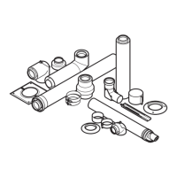
5.18.4 Connecting the product to the air/flue
system
1. Install the product (→ Installation instructions for the
product).
2. Slide the collar (5) onto the air pipe.
3. Install the extension (4) and the elbow (2) between the
connector for the flue pipework.
4. Install the 40 mm air pipe clamp (1). When doing so,
ensure that it is aligned centrally.
5. Install the 70 mm air pipe clamps (3). When doing so,
ensure that they are aligned centrally.
6. Connect all of the pipe joints with air pipe clamps (1).
Condition: Additional extensions and elbows required
▶ Install the extensions. (→ Section 5.19.2)
▶ Install the elbows (→ Section 5.19.4).
▶ Connect all of the pipe joints with air pipe clamps.
(→ Section 5.19.5)
5.19 Installing the sliding sleeve, elbows and
extensions
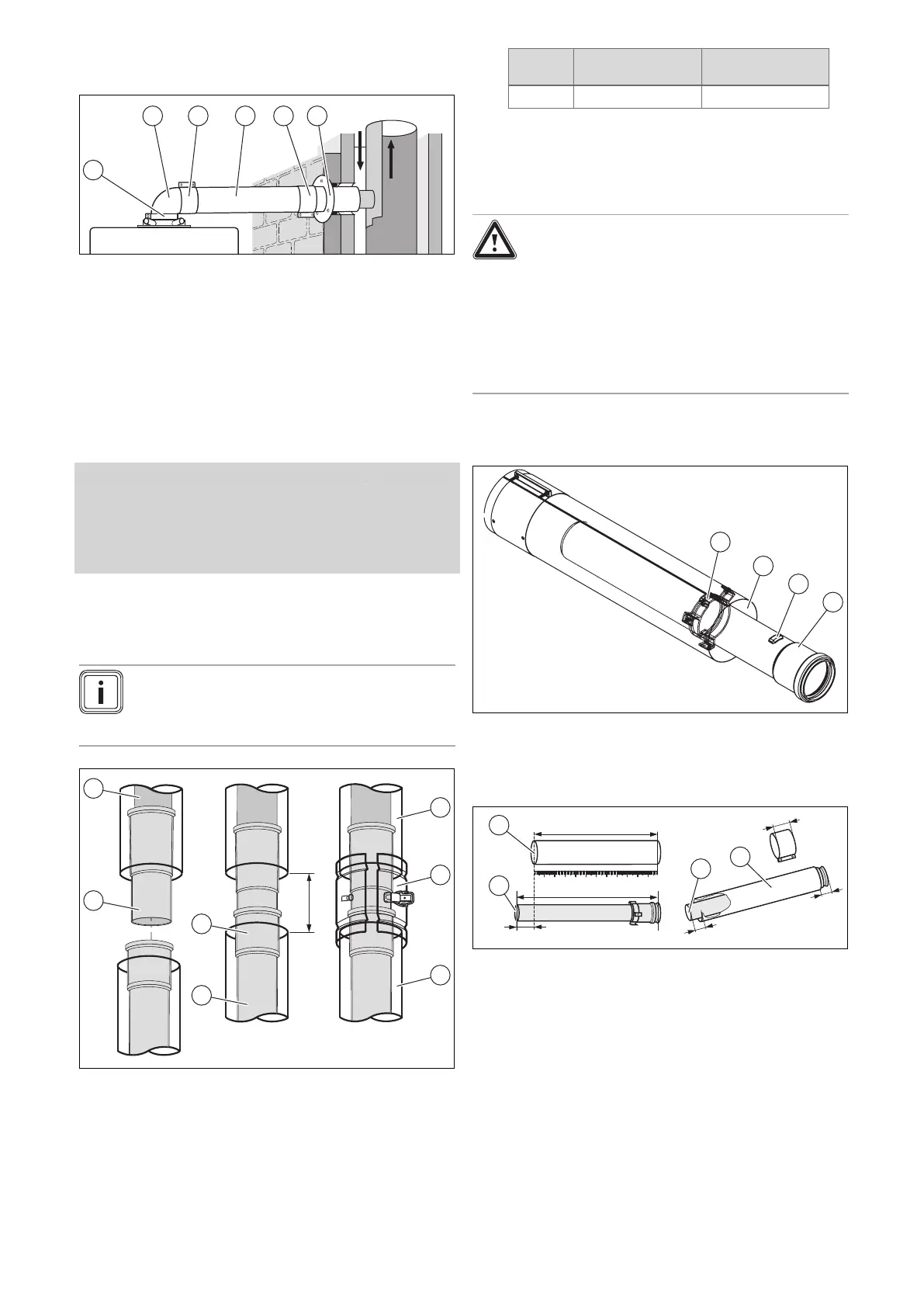
5.19.1 Installing the sliding sleeve
Note
The sliding sleeve provides for straightforward
installation and disconnection of the air/flue pipe
to/from the product.
1. Slide the sliding sleeve (2) onto the flue pipe (1) as far
as it goes.
2. Pull the sliding sleeve (2) back far enough from the flue
pipe (1) so that the inserting end of the sliding sleeve
sits in the sleeve (3) of the flue pipe (4).
60/100 mm dia-
meter
80/125 mm dia-
meter
A 100–110 mm 82–90 mm
3. Connect the air pipes (5, 7) with the air pipe clamp (6).
4. Use a locking screw to secure both sides (→ "Installing
the air pipe clamps" section).
5.19.2 Installing extensions
Danger!
Risk of poisoning due to escaping flue
gas.
The flue pipes of the air/flue pipe may move
as a result of thermal expansion and may
then become disconnected.
▶ Lock the flue pipe in the spacer of the air
pipe.
5.19.2.1 Installing 60/100 mm diameter extensions
1. Turn the flue pipe (1) to a position that enables the
ridge (2) on the plastic pipe to be pushed through the
spacer (4).
2. Pull the pipe quickly and firmly over the detent.
1.
2.
A
B
+ 40 mm
13
70
27
1
2
2
1
3. First, measure the required air pipe length* (A) and
then calculate from that the corresponding flue gas
pipe length (B) in each case:
– Length of the flue pipe: Length of the air
pipe + 40 mm
– Minimum length of air-pipe extension: 80 mm.
4. Shorten the pipes, e.g. with a saw.
5. After shortening it, lock the flue pipe (1) inside the air
pipe (2) again: Push the flue pipe back into the air pipe.
Turn the flue pipe as far as it will go.