52 Air/flue pipe installation manual 8000026412_01
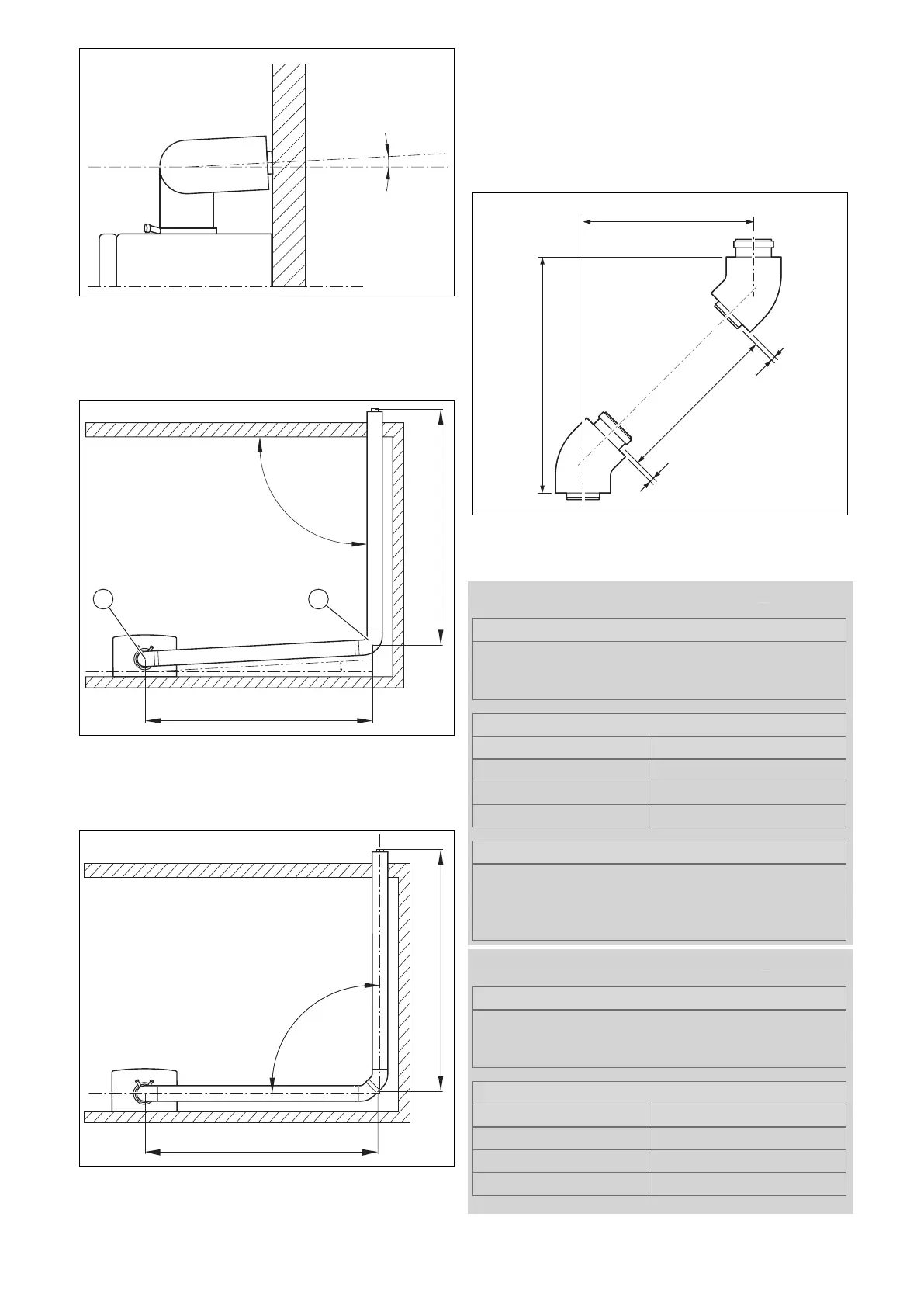
Arrangement of the 2 x 87° elbows – View from the side
▶ When using elbows to route long flue pipework in a
corner, observe the following figures.
Connecting extensions with 87° elbows
max. 5 m
max. 5 m
* = 3°
90°
*
1 2
▶ To ensure that you can guide a second 87° elbow (2) at
a right angle through the wall, install the elbow (1) on the
top of the boiler, at a 3° rotation.
Connecting extensions with 45° elbows
▶ Install an 87° elbow at an angle of 3° between the wall
and the air/flue pipework or use two 45° elbows.
▶ Connect all of the pipe joints with air pipe clamps.
(→ Section 5.19.5)
5.19.4 Calculating the offset dimensions for the
air/flue pipework
5.19.4.1 Calculating the offset dimensions of 45°
elbows (air/flue pipework)
A Offset
B Length of the air pipe
C Height
Validity: Air/flue pipe, 60/100 mm diameter
Formula
B = (A × 1.41) − 130 mm
C = A + 120 mm
Length of the flue pipe = B + 40 mm
Restrictions
Offset (A)
Without extension 90 to 100 mm
With extension 160 to 800 mm
not possible 106 to 154 mm
Example
Required offset (A): 450 mm
B = 450 mm × 1.41 − 130 mm =504 mm
C = 450 mm + 120 = 570 mm
Length of the flue pipe = 504 + 40 mm = 544 mm
Validity: Air/flue pipe, 80/125 mm diameter
Formula
B = (A × 1.41) − 130 mm
C = A + 120 mm
Length of the flue pipe = B + 40 mm
Restrictions
Offset (A)
Without extension 85 to 100 mm
With extension 170 to 730 mm
not possible 101 to 169 mm