8000026412_01 Air/flue pipe installation manual 31
6. If there is sufficient space available, you can use the
sliding sleeve as an alternative to connect the air/flue
pipe. (→ Section 5.19.1)
7. Install all air pipe clamps and secure the air pipe clamp
using the locking screws. (→ Section 5.19.5)
5.13 Direct, rear, telescopic wall duct –
0010039336 – diameter 60/100 mm
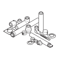
5.13.1 Scope of delivery
498 - 713
40
4
1
Ø165 Ø165
2
3
5
1 Telescopic wall duct
2 Collar (outside)
3 Collar (internal)
4 Locking screws
5 40 mm clamp
5.13.2 Determining the pipe length of the wall duct
1. Measure the clearance Y from the external wall to the
installation surface for the boiler.
2. Set the required pipe length:
– At least: Y + 24 mm
– Maximum: Y + 28 mm
– If the terminal is below a roof overhang or a ho-
rizontal surface, you can pull the wall duct up to
500 mm out of the wall in order to guarantee that
the flue gases are extracted without any obstruc-
tions.
Note
Do not shorten the telescopic flue pipe.
If the required pipe length cannot be
achieved, use extensions or the horizontal
wall/roof duct.
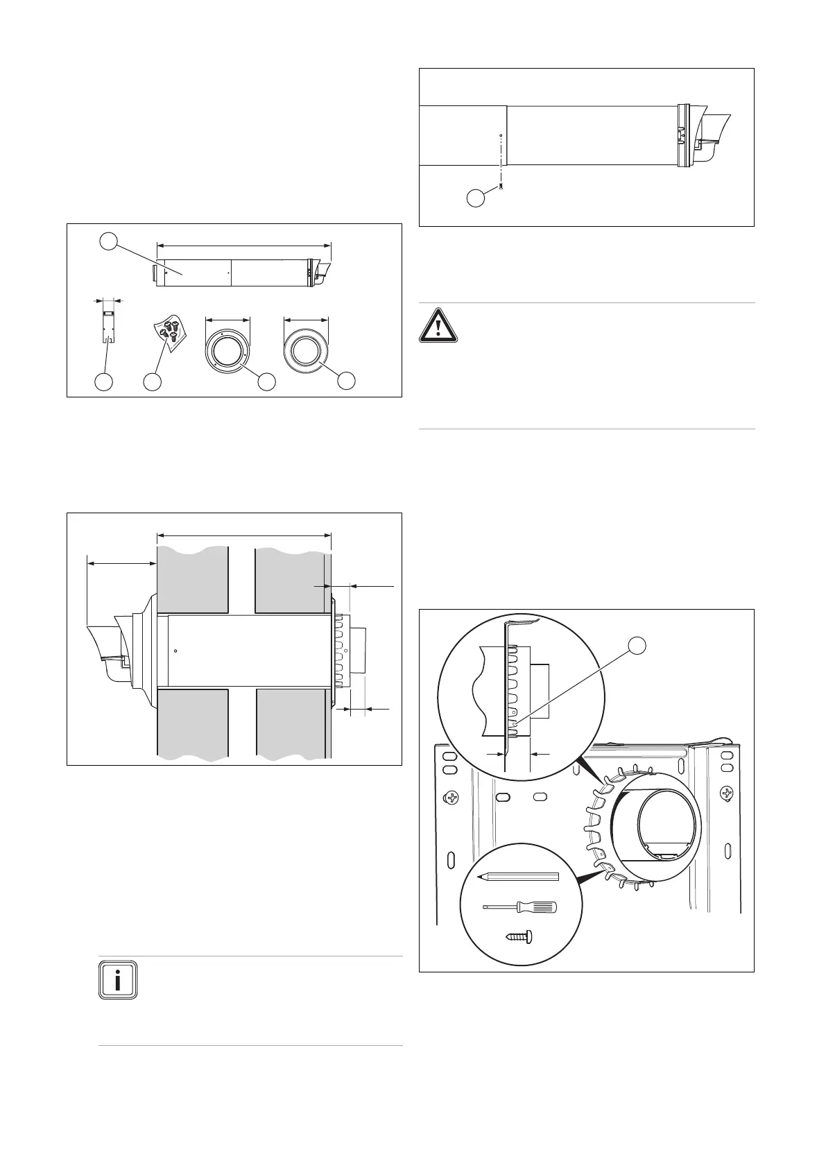
5.13.3 Securing the telescopic pipe
1. Set the telescopic wall duct to the correct length.
– Note that the TOP symbols at both ends must point
upwards.
Danger!
Risk of poisoning due to escaping flue
gas.
Flue gas can escape if a flue pipe is dam-
aged.
▶ Only use the self-tapping screw provided.
2. Secure the air pipes to each other by screwing the
overlapping air pipes together using the supplied self-
tapping screws (1) on both sides.
5.13.4 Installing the wall duct
1. Drill a hole.
– Diameter: 110 mm
2. Push the air/flue pipe from outside and through the wall
and the terminals.
3. Pull the wall duct out to the required depth.
4. Use the locking screws to secure the wall duct.