8000026412_01 Air/flue pipe installation manual 53
Example
Required offset (A): 300 mm
B = 300 mm × 1.41 − 130 mm = 293 mm
C = 300 mm + 120 = 420 mm
Length of the flue pipe = 293 + 40 mm = 333 mm
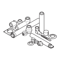
5.19.4.2 Calculating the offset dimensions of 87°
elbows (air/flue pipework)
A Offset
B Length of the air pipe
C Height
Validity: Air/flue pipe, 60/100 mm diameter
Formula
B = A − 200 mm
Length of the flue pipe = B + 40 mm
Restrictions
Offset (A)
Without extension 190 to 200 mm
With extension 271 to 800 mm
not possible 201 to 264 mm
Example
Required offset (A): 350 mm
B = 350 mm − 200 mm = 150 mm
Length of the flue pipe = 150 mm + 40 mm = 190 mm
Validity: Air/flue pipe, 80/125 mm diameter
Formula
B = A − 200 mm
Length of the flue pipe = B + 40 mm
Restrictions
Offset (A)
Without extension 190 to 200 mm
With extension 300 to 960 mm
not possible 201 to 299 mm
Example
Required offset (A): 400 mm
B = 400 mm − 200 mm = 200 mm
Length of the flue pipe = 200 mm + 40 mm = 240 mm
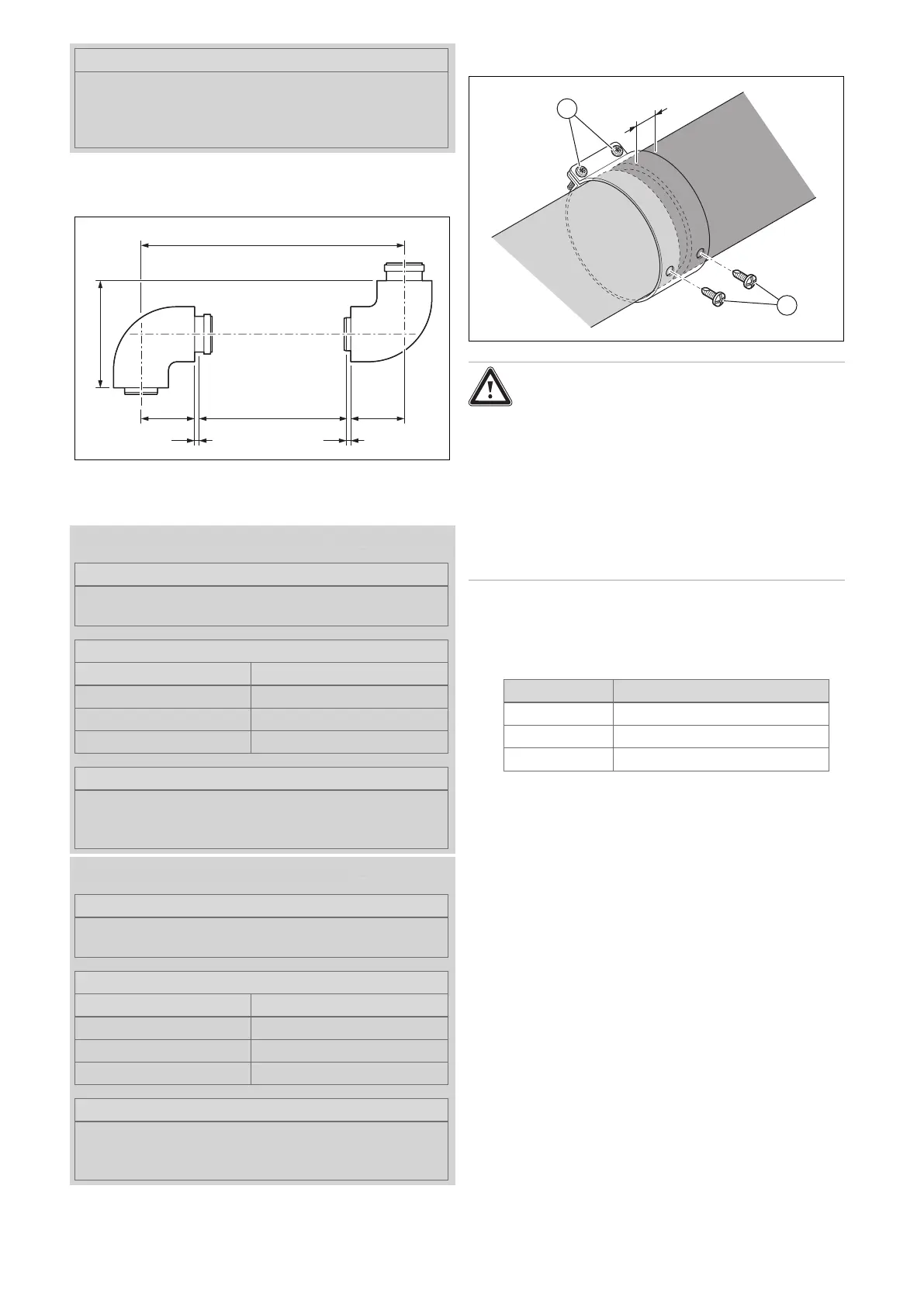
5.19.5 Installing the air pipe clamps
Danger!
Risk of poisoning due to escaping flue
gas.
Flue gas may escape through the damaged
flue pipe or through pipes that have not been
securely connected to each other.
▶ Secure the clamps and air pipes using the
supplied bolts.
▶ Ensure that the flue pipe is not damaged
when tightening screwed connections.
1. Slide the air pipes together.
– Distance between the air pipes: 0 to 5 mm
2. Observe the minimum clearance between the edge of
the pipe clamp and the air pipe.
Air pipe clamp A
min
[mm]
70 mm 30
48 mm 15
40 mm 15
3. Slide the central air pipe clamp over the pipe joint of
the air pipes and tighten the screws (1).
4. Screw in the self-tapping locking screws (2).