Installation and maintenance instructions ecoTEC plus 0020031552_0314
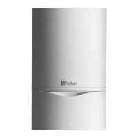
A 100 mm standard flue duct (Item No. 303 933) is
available. Further information can be obtained from the
installation instructions for the flue duct.
Extensions are available to increase this length to a
maximum of 5.5 m. 87° elbows and 45° bends are also
available to increase the flexibility during installation.
3.6.2 Optional 125 mm flue pipe
A concentric flue pipe having an outside diameter of
125 mm is available, which can be extended to a length
of up to 21 m.
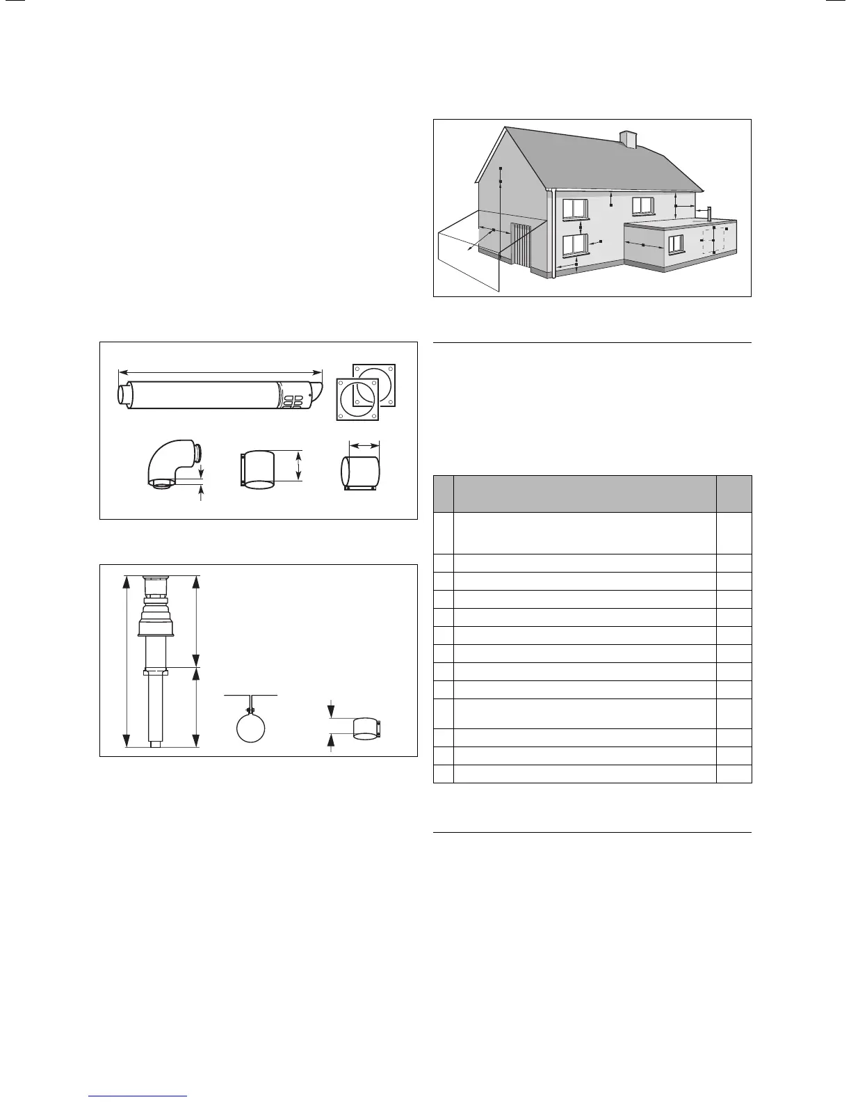
You can also get a vertical system. Further information
can be obtained from the installation instructions for
the flue pipe.
70
1103
70
15
Fig. 3.4 Item No. 303 209
1530
880
650
70
Fig. 3.5 Item No. 303 200 (80/125)
3.7 Flue termination
The following information applies to both flue pipe
systems.
a. The terminal position must be located in such a
position that any flammable gases can be freely
dissipated.
b. A plume of water vapour will sometimes be visible
from the flue terminal. Positions where this could
be a nuisance should be avoided.
c. If the terminal is less than 2 m above a balcony, the
ground or a flat roof that is accessible by persons,
a suitable terminal guard should be fitted (manufac-
tured by Tower Flue Components, Tonbridge, TN9 1TB,
Model K3, plastic-coated).
A
BCD
A
G
H, I
F
J
B
F
M
L
L
K
K
G
G
F
F
E
A
A
Fig. 3.6: Flue termination
h
Note
Vertical flue pipes must not terminate within
600 mm of an opening window, air vent or any
other ventilation opening.
The flue pipe must be fitted, or shielded, in such a way
that ignition or damage to sections of the building are
avoided.
Location of the junction mm
A Directly under or above an opening or the horizontal
to an opening, a hollow ventilation tile, an opening
window etc.
300
B Under gutters, soil pipes or drainpipes 75
C Unter eaves 200
D Under balconies 200
E From vertical drainpipes and down-pipes 25
F From external and internal corners 300
G Above the ground, a roof or a balcony 300
H Opposite another surface 600
I Opposite another termination 1200
J Next to an opening (e.g. a door, window) within a car-
port
1200
K Vertically away from a junction on the same wall 1500
L Horizontally away from a junction on the same wall 300
M Distance away from an adjoining vertical flue pipe 500
Table 3.2 Position of the terminal in a fan-assisted concentric flue
h
Note
In addition, the terminal should not be located
closer than 150 mm from an opening in the fabric
of the building formed for the purpose of accom-
modating a built-in element such as a window.
BS 5440–1: We recommend that the terminal of a
fan-assisted flue system be positioned as follows:
a) At least 2 m from an opening in the building directly
opposite, and
3 General requirements
 Loading...