Installation and maintenance instructions ecoTEC plus 0020031552_0316
3.10.3 Pressure relief valve
The boiler is equipped with a pressure relief valve. This
safety device is required for all sealed central heating
systems, is preset to 3 bar and is fitted with a 15 mm
compression connection for the discharge pipe, whose
diameter must not be less than 15 mm. The pressure
relief valve must not be used for draining purposes.
3.10.4 Pressure gauge
The pressure gauge is fitted to the boiler in the factory
and indicates the pressure of the primary circuit, to
make filling and testing easier.
3.10.5 Heating circuit expansion vessel
The boiler of the ecoTEC series are equipped with a 10 litre
expansion vessel which is suitable for a sealed heating
system with a maximum water volume of 100 litres.
If the nominal capacity of the boiler expansion vessel is
not adequate for the heating system (e.g. when modern-
ising old open systems) an additional expansion vessel
can be fitted outside the boiler. The pressure gauge
must be fitted in the return pipe, in accordance with
BS 5449: Part 1, as close as possible to the boiler.
In Table 3.5 you will find an overview of the required
size of an additional expansion vessel.
Vessel volume
(in l)
Initial system pressure (in bar) 1.0 1.5
Setting of the excess pressure valve (in bar) 3.0
Total water volume of the system (in l)
25 2.7 3.9
50 5.4 7.8
100 10.9 15.6
125 13.6 19.5
150 16.3 23.4
175 19.1 27.3
200 21.8 31.2
225 24.5 35.1
250 27.2 39.0
275 30.0 42.9
300 32.7 46.8
325 35.7 50.7
350 38.1 54.6
375 40.9 58.5
400 43.6 62.4
425 46.3 66.3
450 49.0 70.2
475 51.8 74.1
500 54.5 78.0
With other system volumes than shown above,
multiply the volume by the adjacent factors
0.109 0.156
Table 3.3 Size of an additional expansion vessel
3.10.6 Shift load storage tank expansion vessel
The shift load storage tank is fitted with a 1 litre expan-
sion vessel.
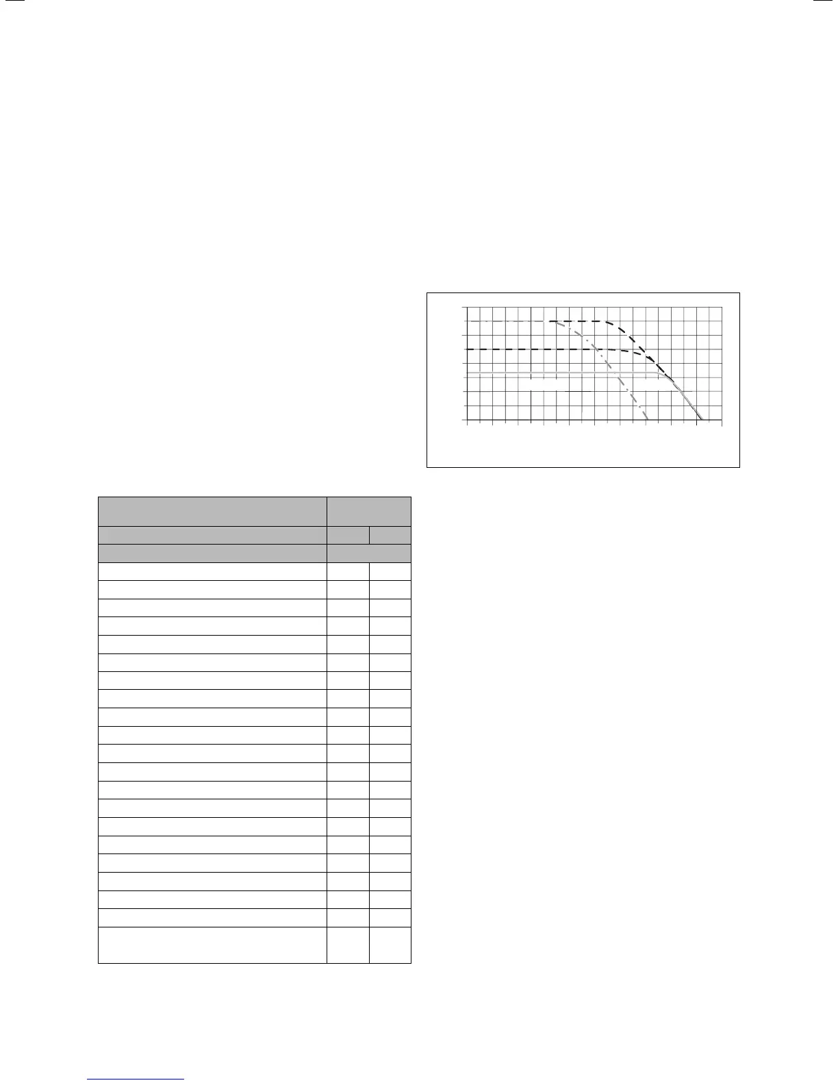
3.11 Details for the pumps
3.11.1 Circulation pump
The circulation pump is integrated in the combi boiler.
The remaining head of the pump with respect to the
bypass valve is shown in Fig. 3.8.
The operating mode of the 2-speed pump can be adjust-
ed using diagnostic number d.19, see Section 8.1.2.
400
300
200
100
0
0 200 400 600 800 1000 1200 1600
Lift
[
mbar
]
Volumeflow
[
l/h
]
18001400
2. Step1. Step
2000
Fig. 3.8 Technical data of the pump in the combi boiler
3.11.2 Shift load storage tank circulation pump
The shift load storage tank is equipped with a mainte-
nance-free charging pump.
3.12 System-Bypass
The boiler is fitted with an automatic system by-pass.
The installation can be used in systems with thermostat-
ic radiator valves without the need for an additional
by-pass. The by-pass valve is adjustable, see Section 5.8.
3.13 Venting
The boiler is fitted with an automatic air vent. Other
measures need to be taken to allow the heating system
to be either automatically or manually vented during
filling and during commissioning.
3.14 Condensate siphonic trap
The boiler is fitted with a siphonic condensate trap
incorpaorating a water seal of 145 mm.
3 General requirements
 Loading...