47Installation and maintenance instructions ecoTEC plus 0020031552_03
8.1.2 Diagnostic codes
In the diagnostic mode, you can change certain parame-
ters or display more information.
The diagnostic information is divided into two diagnostic
levels. Access to the second diagnostic level can only be
permitted after entering a password.
a
Caution!
Danger of incorrect operation and wrong unit
parametrisation!
Access to the second diagnostic level must be
used exclusively by a heating engineer.
First diagnostic level
• Press the "i“ and "+“ buttons simultaneously.
The display shows "d.00“.
• Use the buttons "+“ or "–“ to move to the desired di-
agnostic number of the first diagnostic level (see the
Table 8.2).
• Press the "i" button.
The associated diagnostic information is shown in the
display.
• If necessary you can change the value with the but-
tons "+“ or "–“ (display flashing).
• Save the new value by holding down the "i“ button for
approx. 5 seconds until the display no longer flashes.
You can end the diagnostic mode as follows:
• Press the "i“ and "+“ buttons simultaneously. or
• Do not press any button for about 4 minutes.
The current heating flow temperature appears in the
display again.
Troubleshooting 8
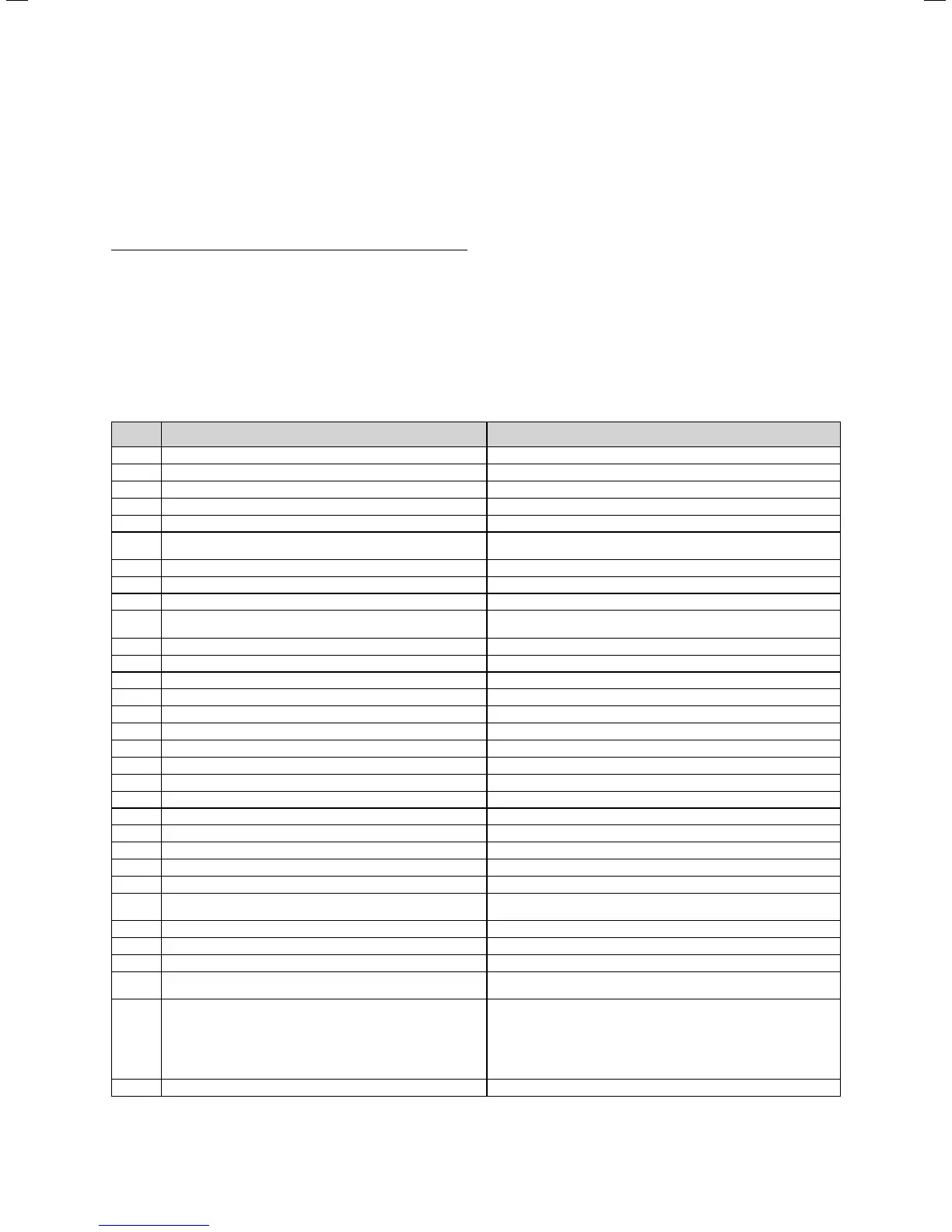
Display
Meaning Displayed value/settable value
d.0 Heating partial load Adjustable heating partial load in kW (factory setting: max. output)
d.1 Water pump over run time for heating mode 2 - 60 minutes (factory setting: 5 minutes)
d.2 Max. anti cycle time heating at 20°C flow temperature 2 - 60 minutes (factory setting: 20 minutes)
d.3 Measured value of the domestic hot water temperature in °C
d.4 Measured value for the warmstart sensor in °C
d.5 Flow temperature target value or return temperature tar-
get value, if return flow regulation selected
in °C, max. of the value set in d.71
limited by an eBUS controller, if fitted)
d.6 Hot water target temperature in °C, 35 to 65 °C
d.7 Warm start target temperature in °C, 40 to 65 °C
d.8 Heat demand of external controllers (terminal 3-4) 1=closed (heating requirement); 0=opened (no heating requirement)
d.9 Flow target temperature from external analogue regulator
to terminal 7-8-9/eBus
in °C, minimum from ext. eBus target value and target value
terminal 7
d.10 Status internal heating pump 1, 2 = on, 0 = off
d.11 Status external heating pump (via accessory module) 1 to 100 = on, 0 = off
d.12 Cylinder charging pump (via accessories module) 1 to 100 = on, 0 = off
d.13 External hot water circulation pump (via accessory module) 1 to 100 = on, 0 = off
d.22 Hot water demand 1 = on, 0 = off
d.23 Summer /winter function 1 = Winter, 0 = Summer
d.25 Hot water activation via eBUS controller 1 = yes, 0 = no
d.30 Control signal for both gas valves 1 = on, 0 = off
d.33 Fan speed target value in upm/10
d.34 Fan speed actual value in upm/10
d.35 Internal diverter valve position 0 = heating; 100 = hot water; 40 = mid-position
d.36 Hot water flow sensor in l/min
d.40 Flow temperature actual value in °C
d.41 Return flow temperature actual value in °C
d.44 digitalised ionisation voltage Display range 0 to 102, >80 no flame, <40 good flame display
d.47 External temperature (only on weather-compensated
Vaillant controllers)
actual value in °C
d.67 Remaining burner anti-cycling time in minutes
d.76 Unit variants (device specific number) 00 to 99
d.90 Status of the digital controller 1 = identified, 0 = unidentified (eBUS Address <=10)
d.91 DCF status with connected external probe with DCF77 re-
ceiver (not available in the UK)
0 = no reception, 1 = reception, 2 = synchronised, 3 = valid
d.92 Module recognition shift load storage tank Setting range:
0 = not recognised
1 = no communication via PE-BUS; Module recognised earlier
2 = Communication OK
Setting = 0: Unregister shift load storage tank from combi boiler
(if shift load storage tank is to be de-installed, set d.92 = 0)
d.97 Activation of the second diagnostic level Password: 17
Table 8.2 Diagnostic codes of the first diagnosis level
 Loading...