53Installation and maintenance instructions ecoTEC plus 0020031552_03
5
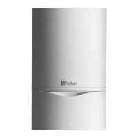
Fig. 9.3 Gas valve/fan screwed joint
• Release both fixing screws (5) on the gas valve and
remove the fan from the gas valve.
• Replace the faulty component.
a
Caution!
Danger of damage to the equipment!
Fit the gas valve and fan in the same position
as before.
• Screw the fan onto the gas valve.
Use new seals.
• Re-install the complete "gas valve/fan" unit in reverse
sequence.
• After completion of the work check the system for gas
leaks and carry out a function test (see Section 7.8).
9.4 Replacing the expansion vessel
d
Danger!
Before replacing components ensure that the
safety instructions from Section 9.1 are ob-
served.
• Disconnect the appliance from the mains as described
in Chapter 9.1, and close the gas isolator valve in the
gas supply pipe.
• Close the stop valves in the flow and return pipes and
drain the water out of the combi boiler.
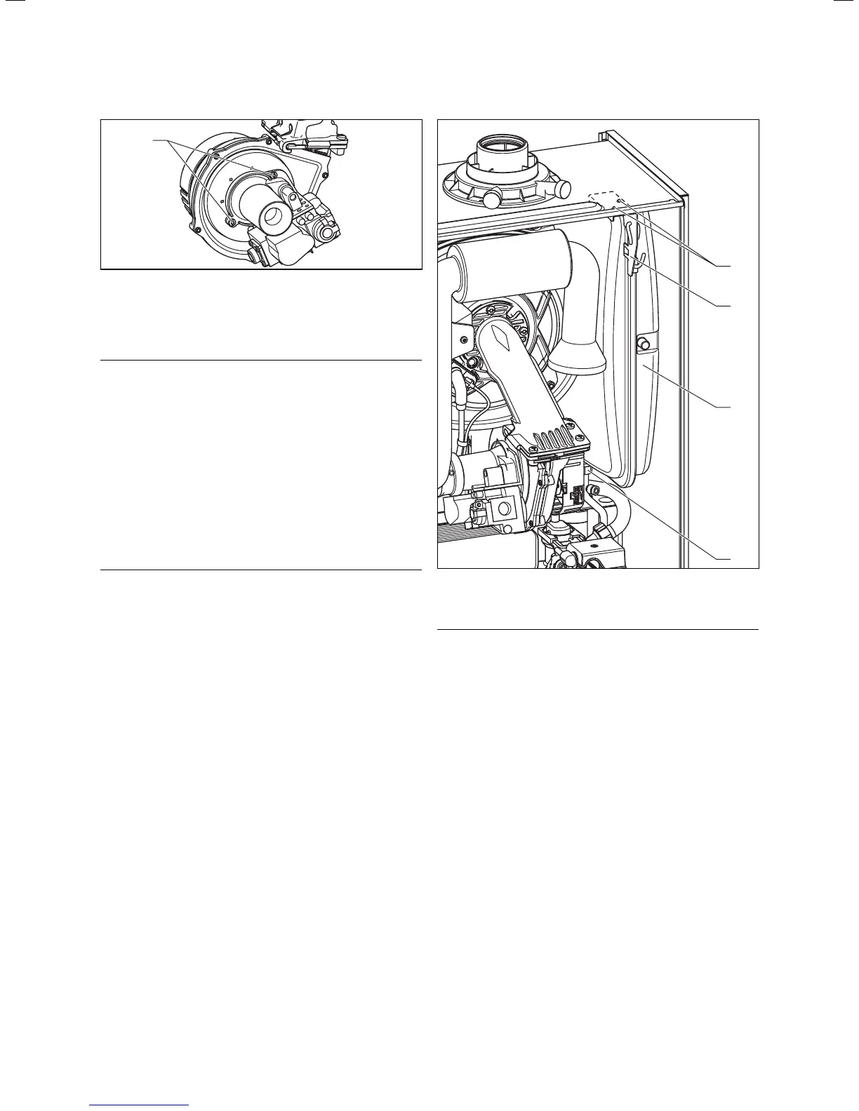
• Unscrew the nuts (4) from the water pipe on the un-
derside of the expansion vessel.
• Unscrew the two screws (1) in the retaining plate (2)
and remove the retaining plate.
• Pull out the expansion tank (3) forwards.
• Guide the new expansion tank back into the appliance.
• Re-connect the new expansion tank using a new gas-
ket.
• Re-fit the retaining plate.
• Check the pressure of the expansion tank (minimum
pressure 0.75 bar).
If required, match the pressure to the static head of
the heating system.
• Fill and vent the combi boiler.
• After completion of the work check the system for gas
leaks and carry out a function test (see Section 7.8).
1
2
3
4
Fig. 9.4 Replacing the expansion vessel
9.5 Replacing the primary heat exchanger
d
Danger!
Before replacing components ensure that the
safety instructions from Section 9.1 are ob-
served.
• Disconnect the appliance from the mains as described
in Chapter 9.1, and close the gas isolator valve in the
gas supply pipe.
• Close the stop valves in the flow and return pipes and
drain the water out of the combi boiler.
• Remove the compact thermo module as described
under 7.2.1.
• Remove the expansion tank as described under 9.4.
• Pull off the condensate pipe which runs from the pri-
mary heat-exchanger to the siphon.
• Remove the clamps (1) and (2) and pull off the flow
and return hoses from the primary heat-exchanger.
• Unscrew the four screws (3) on the holder of the pri-
mary heat-exchanger.
Replacing components 9
 Loading...