41Installation and maintenance instructions ecoTEC plus 0020031552_03
7.1.4 Function check of the combination boiler
• Carry out a function check of the combi boiler as de-
scribed earlier.
• Remove the front panel in accordance with the in-
structions and switch the combi boiler on.
• Check the function of the burner through the sight glass.
• Check that the flames consistently cover the surface
of the burner.
• Take particular notice if the height of the flame is ex-
cessive and the production of soot.
7.2 Maintenance of the thermo-compact module
7.2.1 Remonving the thermo-compact module
2
3
1
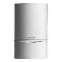
Fig. 7.1 Removing the air inlet pipe
The thermo-compact module consists of the burner, the
fan, the gas valve and the gas supply (mixture pipe).
d
Danger!
There is danger of being burned or injured by
the compact thermal module and at all compo-
nents carrying water. Only carry out work on
these components once they have cooled down.
Proceed as follows to remove it:
• Switch the combi boiler off.
• Isolate the power supply from the combi boiler.
• Remove the bottom cover (if fitted) of the combi boil-
er by releasing both the spring clips and lowering the
back of the bottom cover downwards.
• Pull the bottom cover slightly towards the back
• Remove the bottom cover from the unit.
• Turn the stop valve off.
• Turn the stop valves of the central heating off.
• Release the screw and the spring clips on the front
panel located under the front of the unit.
• Remove the front of the of the unit by pulling the bot-
tom edge forwards and lifting slightly.
• Lower the electronic box.
• Unscrew the screw (2) and remove the air inlet pipe (1).
• Separate the gas supply line (3) from the gas valve.
Make sure that the corrugated gas pipe does not twist
by holding the flattened end of the pipe with an open-
ended spanner whilst you release the cap nut.
a
Caution!
Danger of damage to the corrugated gas pipe!
Under no circumstance may the compact ther-
mal module be suspended from the flexible cor-
rugated gas pipe.
10
11
9
8
4
5
6
7
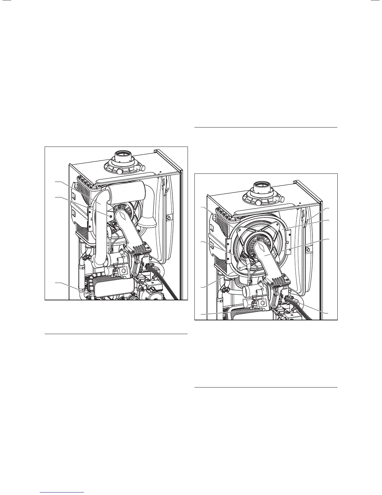
Fig. 7.2 Removal of the thermo-compact module
• Pull the ignition cable (5) and the earth wire (6) off
the ignition electrode.
• Unscrew the four nuts (4) from the burner door.
• Pull the two electrical connections (7 and 8) off the
fan and the gas valve.
• Pull the burner, gas valve and fan assembly (9) forwards
off the integral condensation heat-exchanger (10).
h
Note
You can hang the thermo-compact module on
the hook (11) whilst you perform the mainte-
nance work.
• After removing the thermo-compact module clean the
components in accordance with the following descrip-
tion.
Inspection and maintenance 7
 Loading...