21Installation and maintenance instructions ecoTEC plus 0020031552_03
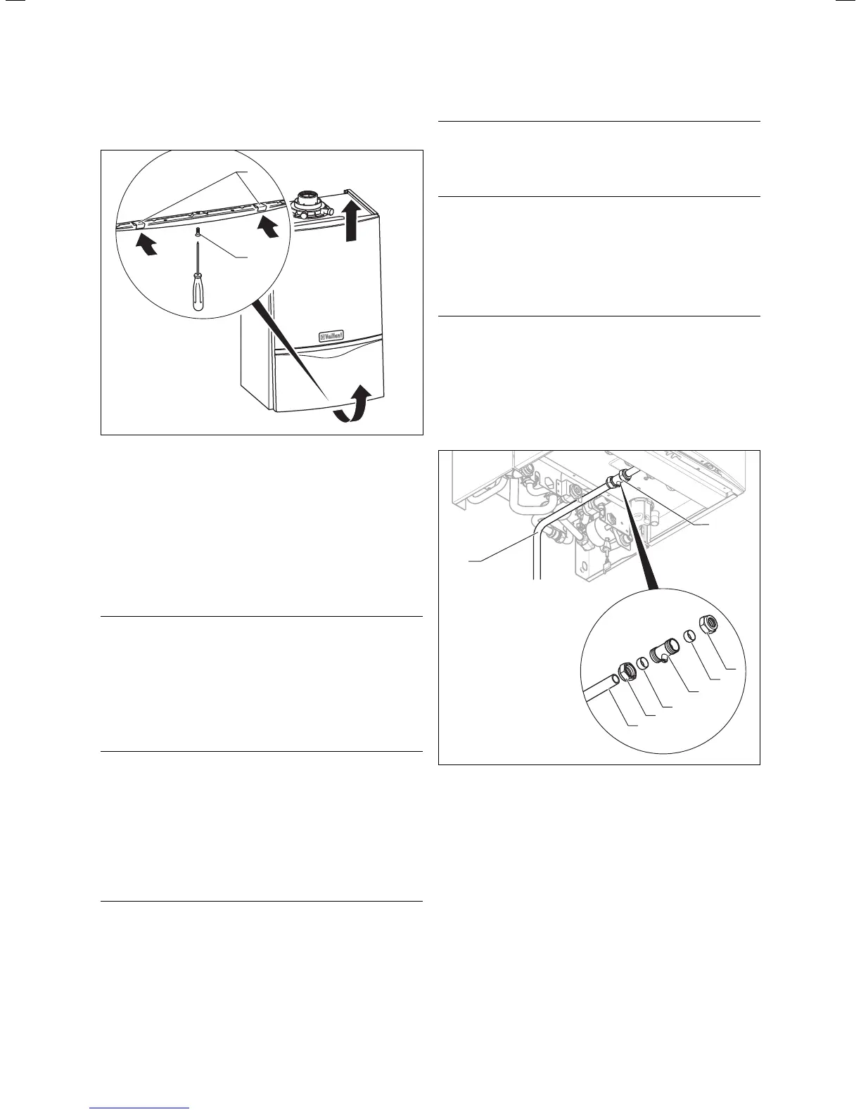
4.9 Removing the front case
1
2
Fig. 4.5 Removing/fixing the front case
Proceed as follows to remove the front cladding:
• Release the screw (1) on the base of the unit.
• Push the two retaining clips (2) on the base of the
unit inwards until the front case releases.
• Hold the front case by the bottom edge, pull forwards
and remove the front case from the unit.
4.10 General instructions concerning the heating
system
a
Caution!
Clean the heating system thoroughly before
connecting the appliance!
This will remove small particles such as solder
residues, ash, hemp, putty, rust, dirt particles
and similar substances from the pipework.
Otherwise there is a danger that these particles
can deposit in the appliance and cause damage.
h
Note
The heating system is fitted with an expansion
tank (10 l/0.75 bar).
• Before connecting the unit, make sure that this volume
is adequate. Otherwise the installation must be fitted
with an additional expansion vessel (see Section 3.11.6).
4.11 Gas connection
d
Danger!
Danger of death by gas escapes if the installa-
tion is not properly carried out!
The gas connection must only be made by
a competent person (e.g. CORGI registered).
The legal directives and local regulations for
the gas supply companies must be observed.
a
Caution!
Danger of leaks by improper installation!
Ensure a stress-relief assembly of the gas
pipes.
a
Caution!
Danger of damage to units and system!
The electronic gas valve may be tested for
leakage only with a maximum pressure of
150 mbar!
At higher testing pressures there is a danger
that the gas fitting could be damaged.
a
Caution!
Danger of damage to the gas isolator valves by
heat transmission!
If the final connections to the combi boiler are
made using soldered pipe connections, you
must be particularly careful not to damage the
gas isolator valves by heat transfer.
2
1
3
6
2
4
5
1
Fig. 4.6 Gas connection
Proceed as follows for gas connection:
• Remove the gas connection pipe elbow (2) and gas
isolator valve (1) from the packaging.
• Push the union nut (3) and the olive (4) onto the gas
pipe which protrudes from the combi boiler.
• Push the gas isolator valve (1) onto the gas pipe which
protrudes from the combi boiler up to the stop.
• Pull the union nut (3) with the olive (4) towards the
gas isolator valve. Tighten the union nut hand tight.
• Push the union nut (6) and the olive (5) onto the gas
connection pipe elbow (2).
• Push the gas connection pipe elbow (2) into the gas
isolator valve (1) up to the stop.
Sequence of operations during installation 4

 Loading...