25Installation and maintenance instructions ecoTEC plus 0020031552_03
4.17 Storage tank pressure relief discharge pipe-
work
1
2
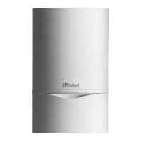
Fig. 4.14 Storage tank pressure relief discharge pipe connection
The safety valve for the hot water system is integrated
in the shift load storage tank.
• Remove the flexible drain hose from the box of acces-
sories for the shift load storage tank.
• Push the drain hose (1) onto the safety valve (2).
The end of the drain hose can be directed via an open
connection to a tundish and terminated in a similar
manner to the boiler pressure relief discharge pipe.
4.18 Connecting the flue system to the combina-
tion boiler
• Refer to the separate air/flue duct installation instruc-
tions included with the appliance.
4.19 Electrical connection
4.19.1 General requirements
e
Danger!
Risk of fatal electric shock from touching live
connections!
Before working on the appliance, turn off the power
supply and secure against restart! All work on the
electrical system should be carried out by a com-
petent person and must be in accordance with
BS 7671 (IEE Regulations). In the Irish Republic
the current issue of the ETCI Regulations (Electro-
Technical Council for Ireland) must be observed.
a
Caution!
For the electrical connection observe the relevant
installation instructions for the ecoTEC combi
boilers and the country-specific regulations.
The appliance is designed for connection to 230 V,
~ 50 Hz supply with a 3 A rating. Connection to the
mains supply shall be made via a fused 3 pin plug to an
unswitched shuttered, and should comply with BS 1363.
(Alternatively the connection can also be carried out
with a 3 A fused two-pole isolator, whose contact sepa-
ration at all poles is at least 3 mm and which supplies
only the appliance and controls). The connection must
permit complete isolation of the appliance and its con-
nected controller from the mains supply. It should be
easily accessible and be located in the proximity of the
combi boiler. Use a three core flexible cable in accordance
with BS 6500, Tables 6, 8 or 16 (3 x 0.75 to 3 x 1.5 mm
2
).
e
Danger!
Danger of death by electric shock!
The unit must be earthed.
e
Danger!
Danger of death by electric shock!
The power connections L and N continue to be
under power when the main switch of the combi
boiler is switched off.
a
Caution!
Danger of damage to the equipment!
Do not connect mains 230 V power to the ter-
minals 7-8-9 or eBUS (+, -).
h
Note
Ensure that all wiring passes through the cable
clamps in the rear of the control box and are
securely fixed.
• Check that when connecting the mains wiring that the
current carrying conductors become taut before the
earth conductor should the supply cable slip from the
cable clamp.
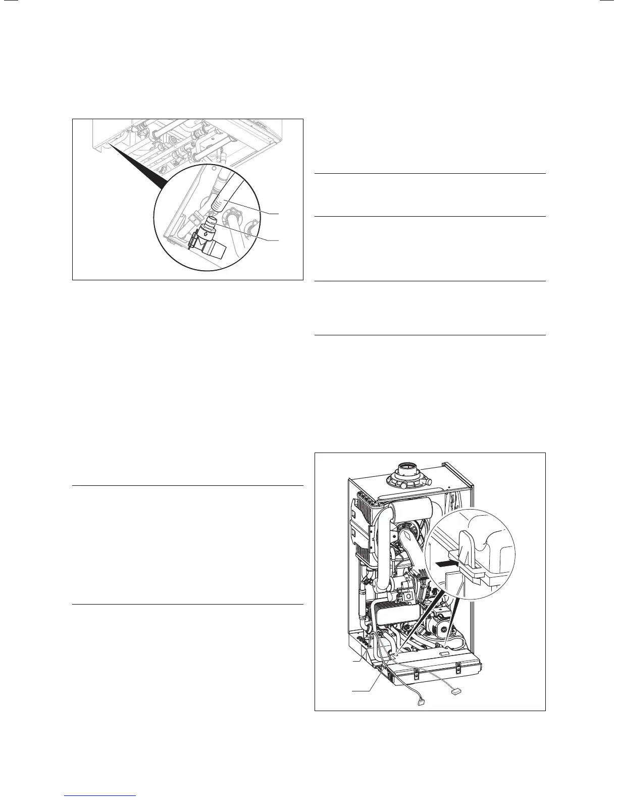
4.19.2 Connecting shift load storage tank
1
2
X12
X31
Fig. 4.15 Opening the electronics box
Sequence of operations during installation 4
 Loading...