Installation and maintenance instructions ecoTEC plus 0020031552_0352
9 Replacing components
The tasks listed below may only be undertaken by a
qualified competent heating engineer.
• Only use genuine spare parts for repairs.
• Check that the parts are correctly fitted and that the
original location and alignment is maintained.
9.1 Safety instructions
d
Danger!
Every time components are replaced observe
the following safety instructions for your own
safety and to prevent damage to the unit!
Take the appliance out of operation.
e
Danger!
Danger of death by electric shock!
Before starting any maintenance work:
Isolate the unit from the electrical mains by
pulling the plug out of the plug socket (if only
an isolator switch is available, remove the fuse
from the switch.)
• Close the stop valves in the gas supply and in the
heating flow and return pipes.
• Close the cold water inlet stop valve (only on combi
boilers).
• Drain the unit if you wish to replace water-conducting
components in the unit.
• Make sure that no water drips on live electrical com-
ponents (e.g. electronic box etc.)!
• Use only new gaskets and O-rings!
• Check the system for gas leaks after completion of
the work. Carry out a function test (see Section 7.8).
• After all maintenance work and after replacing electri-
cal components check the earthing, polarity and earth
resistance using a multi-meter.
9.2 Replacing the burner
d
Danger!
Before replacing components ensure that the
safety instructions from Section 9.1 are ob-
served.
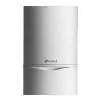
1
Fig. 9.1 Replacing the burner
• Dismantle the compact thermo module as described
under 7.2.1.
• Release the 4 screws (1) on burner, and remove the
burner.
• Mount the new burner with a new gasket. The notch in
the burner must be aligned with the sight glass of the
burner.
• Fit the compact thermo module as described under
7.2.4.
• Fit a new burner door seal kit.
• After completion of the work check the system for gas
leaks and carry out a function test (see Section 7.8).
h
Note
A new burner door seal kit must be fitted every
time the burner door is removed.
9.3 Replacing the fan or gas valve
d
Danger!
Before replacing components ensure that the
safety instructions from Section 9.1 are ob-
served.
• Switch the combi boiler off.
• Isolate the electrical supply from the combi boiler.
• Remove the air intake pipe (Fig. 7.1, Pos. 2).
• Loosen the gas supply pipe on the gas valve (Fig. 7.2,
Pos. 3).
1
3
2
4
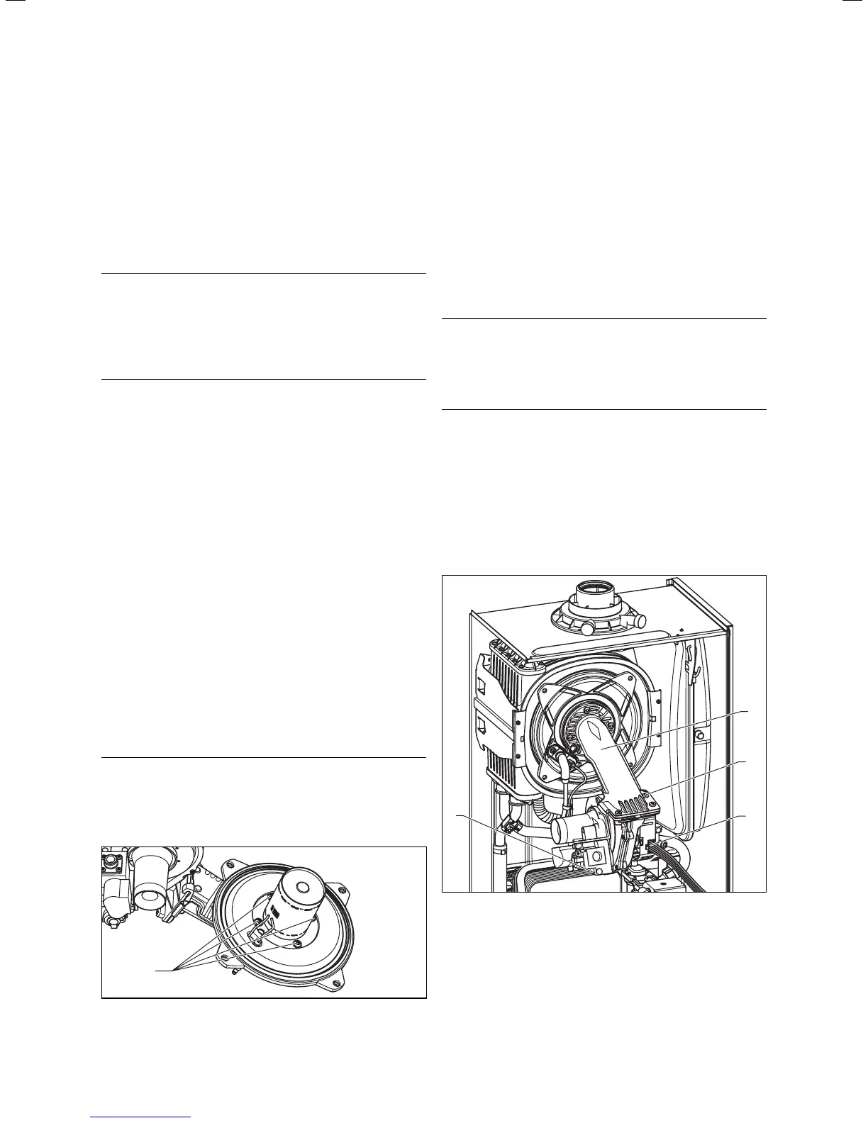
Fig. 9.2 Removing the fan with gas fitting
• Pull the plug (4) out of the gas valve.
• Pull the plug (3) out of the fan.
• Unscrew the three screws (2) out of the thermo-com-
pact module (1).
• Remove the complete component group "gas valve/
fan".
9 Replacing components
 Loading...