19Installation and maintenance instructions ecoTEC plus 0020031552_03
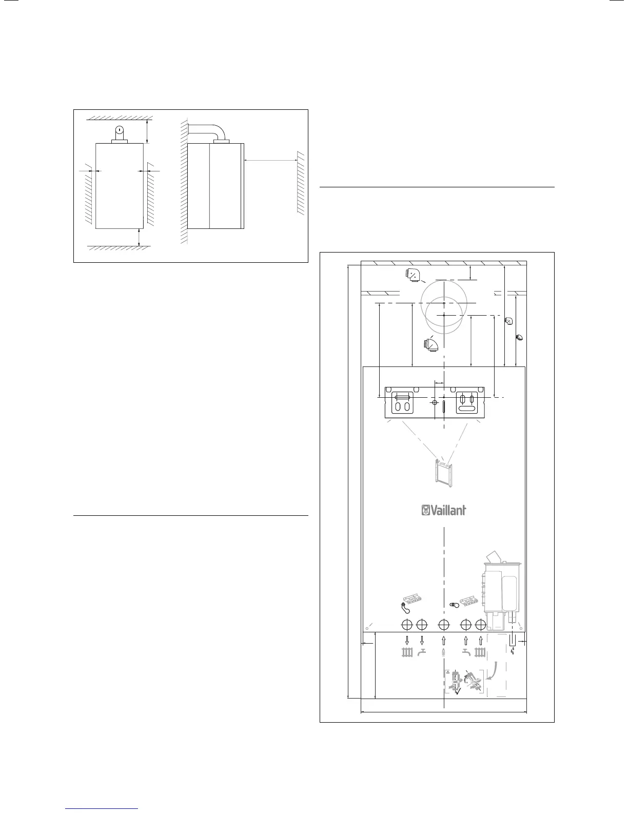
4.2 Required minimum gaps/assembly clearances
min
min 5
min 5
min 500
min 180
165/246
Fig. 4.1 Distances during installation (dimensions in mm)
The combination of units must be installed on a flat
vertical wall which is large enough for the shift load
storage tank with mounted combi boiler, including the
required minimum clearances and space allowances for
installation. The required minimum clearances during
installation can be taken from Fig. 4.1.
The minimum clearances and installation clearances are
shown on the installation template. They are:
– 5 mm on each side of the unit combination
– 180 mm underneath the unit combination
– 165 mm above the boiler if using a flue pipe of 100 mm
outside diameter
– 246 mm above the boiler if using a flue pipe of
125 mm outside diameter
– 500 mm in front of the unit combination to permit
easy access for service work.
Please note that, under the unit combination, there
should be adequate space to position the drain pipes via
a drain funnel. The drain must be visible!
h
Note
If the boiler is to be installed in a timber framed
building, it should be fitted in accordance with
IG/UP/7 Edition 2 „Gas installations in timber
framed and light steel framed buildings“.
4.2.1 Selecting the location for the shift load
storage tank and combination boiler
The installation location for the shift load storage tank
and the combi boiler should be selected so that:
– there is adequate room around the boiler for service
and maintenance work
– the flue pipe of the combi boiler can operate properly
i.e. the location of the terminal of the flue pipe is
located in accordance with these instructions and the
flue pipe is installed in accordance with the installation
instructions for the flue pipe provided
– all the required pipework including the pressure relief
valve and the condensate drain can be fitted.
Further information concerning the installation location
of the combi boiler can be found in the Section "Installa-
tion Location".
4.3 Unpacking the equipment
First cut through the two plastic straps when unpacking
the units. Then open the box and lift the top section of
the polystyrene off. Lift the box upwards.
h
Note
Please take care that the white surface of the
units is not damaged.
4.4 Using the installation template
0020039975_00 10 2006
180
60/100
140
195 ( )
40
60/100
173
276 ( )
80/125
80/125
(Art.-Nr. 303210)
(Art.-Nr. 303910)
5
5
223
256
A
A
25
A
A
A
1176
450
Fig. 4.2 Assembly template
Sequence of operations during installation 4

 Loading...