2. Product overview
HMP series probes are humidity and temperature measurement probes with a digital output
(Modbusâ protocol). The probes are designed for demanding humidity and temperature
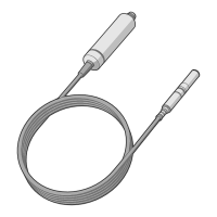
measurement applications. The probes have a two-part structure, with measurement
electronics contained in the probe body and sensor(s) in the probe head. The probe body and
the probe head are connected by a cable, except on the HMP1 model. Length options for this
connecting cable depend on the probe model.
The probes are compatible with Vaisala Indigo transmitters. They can also be connected to
Vaisala Insight software for configuration, calibration, adjustment, diagnostics, and temporary
online monitoring.
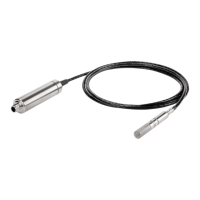
2.1 Probe structure
Figure 1 Probe parts
1 Protection cap (remove before use)
2 5-pin M12 connector
3 Probe body with type label
4 Status indicator LED:
Green Power on and probe online,
flashes when communicating
Red Error
O Power o, or indicator
disabled
5 Probe cable. HMP1 model does not
have a probe cable, as its probe head
is directly attached to the probe body.
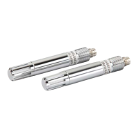
6 Probe head (HMP7 model shown)
7 Location of sensor(s) on the probe
head. Other probe models have a
removable filter over the sensors but
HMP1, HMP9, and TMP1 do not.
8 Protection cap (remove before use)
To prevent the warming of the indicator LED from causing a slight measurement
error, HMP1 keeps the indicator normally o (even when power is on). If the probe
is in error state, the red LED is shown.
2.2 Basic features and options
• Comprehensive list of output parameters. See Output parameters (page 13).
HMP Series with MMP8 and TMP1 User Guide M212022EN-F
12