1. Use a 4-mm Allen key to open the hex screws and remove the top part of the probe
holder.
2. Hold the base part against the mounting surface and mark the locations of the 2 screw
holes.
3. Drill holes at the marked locations using a 6-mm drill bit. Make the holes at least 30 mm
deep.
4. Insert the wall plugs in the holes.
5. Mount the base part using screws.
6. Insert the probe body in the holder.
7. Place the top part on the base and tighten the hex screws with a 4-mm Allen key.
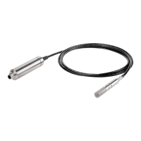
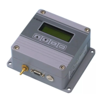
4.2 Wiring
Figure 4 M12 5-pin A-coded male connector pinout
Pin #
Function Notes Wire colors in Vaisala cables
1 Power supply Operating voltage:
• HMP7: 18 ... 30 V DC
• Other models: 15 ... 30 V DC
Current consumption: 10 mA typical,
500 mA max.
Brown
2 RS-485 - White
3 Power GND and
RS-485 common
Blue
4 RS-485 + Black
5 Not connected Gray
HMP Series with MMP8 and TMP1 User Guide M212022EN-F
22