2.10 Thermal overload protection
T> (49)
VAMP 24h support phone +358 (0)20 753 3264
Heat capacitance, service factor and ambient temperature
The trip level is determined by the maximum allowed
continuous current I
MAX
corresponding to the 100 %
temperature rise
TRIP
i.e. the heat capacitance of the motor or
cable. I
MAX
depends of the given service factor k and ambient
temperature
AMB
and settings I
MAX40
and I
MAX70
according the
following equation.
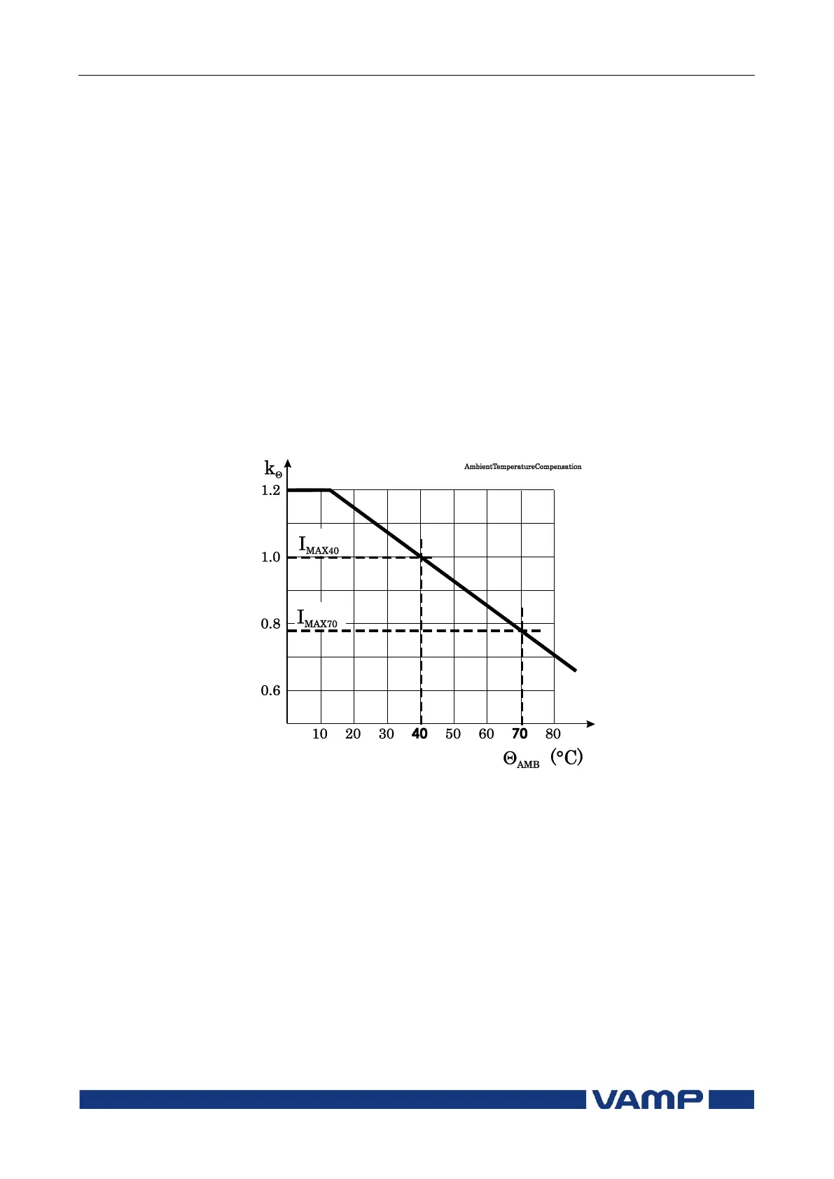
The value of ambient temperature compensation factor k
depends on the ambient temperature
AMB
and settings I
MAX40
and I
MAX70
. See Figure 2-9. Ambient temperature is not in use
when k = 1. This is true when
I
MAX40
is 1.0
Samb is “n/a” (no ambient temperature sensor)
TAMB is +40 °C.
Figure 2-9 Ambient temperature correction of the overload stage T>.
Example of a behaviour of the thermal model
Figure 2-10 shows an example of the thermal model behaviour.
In this example = 30 minutes, k = 1.06 and k = 1 and the
current has been zero for a long time and thus the initial
temperature rise is 0 %. At time = 50 minutes the current
changes to 0.85xI
MODE
and the temperature rise starts to
approach value (0.85/1.06)
2
= 64 % according the time constant.
At time=300 min, the temperature is about stable, and the
current increases to 5 % over the maximum defined by the
rated current and the service factor k. The temperature rise
starts to approach value 110 %. At about 340 minutes the
temperature rise is 100 % and a trip follows.