Installation Installing a Siphon Assembly
25
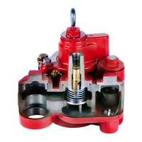
Figure 20. Siphon Ports
6. Remove the 1/4’’ NPT plug from the siphon outlet port and attach siphon system tubing.
Before installing pipe threads, apply an adequate amount of fresh, UL classified for
petroleum, non-setting thread sealant. Apply sealant in a manner that prevents it from
entering and contaminating hydraulic cavities.
7. Turn the service screw counterclockwise all the way up. As the screw approaches its top position, the check
valve will drop into position.
8. Replace the protective plug over the service screw and fully thread into place to ensure a good seal.
9. Turn the air purge screw 2 - 3 turns counterclockwise (see Figure 20).
The air purge screw is retained by a hitch pin to limit travel. Do not attempt to rotate
beyond 3 turns.
10. Turn the pump on and let it run for about 2 minutes to purge air from the manifold’s hydraulic cavities. While
the pump is still running, turn the air purge screw clockwise until it is completely closed.
11. If applicable, open the ball valve down line from the pump.
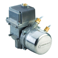
Figure 21. Inserting Siphon Assembly Into Manifold
Siphon port - attach siphon tubing here
Spare vacuum port
Air purge screw
Service screw - accessible
after removing protective plug
Siphon cartridge
rjpumps/fig20.eps
Equipotential bonding
terminal
Siphon port plug upper o-ring
(-121 [1.049'' ID x 0.103'' wide])
Siphon assembly upper o-rings
(-121 [1.049'' ID x 0.103'' wide])
Siphon port plug lower o-ring
(-117 [0.799'' ID x 0.103'' wide])
Siphon assembly lower o-ring
(-117 [0.799'' ID x 0.103'' wide])