Console Installation Console Dimensions
7
Console Dimensions
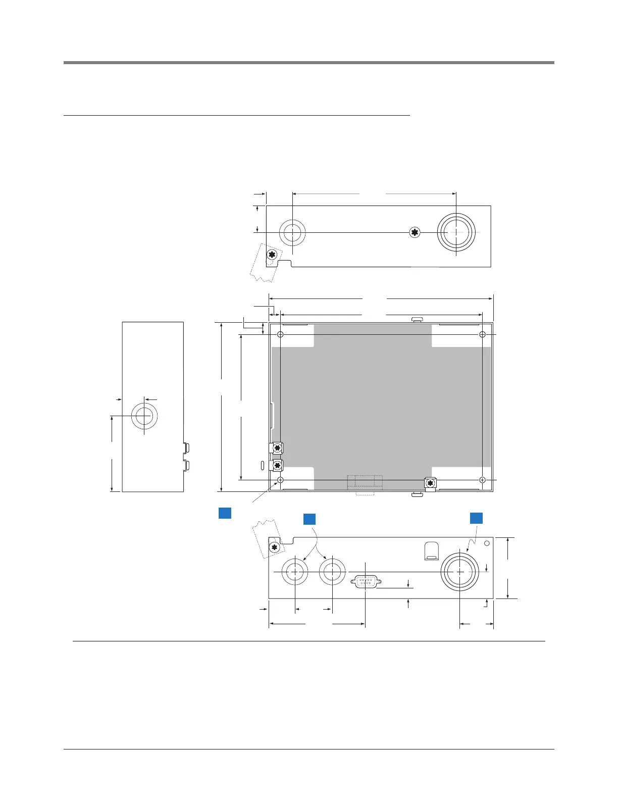
Figure 2 shows the console dimensions, mounting hole pattern, and designated knockouts through which power
wiring and intrinsically safe wiring must enter the console.
Figure 2. Console Dimensions and Designated Wiring Entry Knockouts
Legend for numbered boxes
1 Console mounting holes - 4 places.
2 1/2-inch I.P.S. & 0.56 inch (22 and 14 mm) - Power wiring only conduit knockouts (4 places).
3 1/2-, 3/4-, & 1-inch I.P.S. (22, 28, & 35 mm) - Intrinsically safe only conduit knockouts (2 places).
0.34''
(8,6 mm) typ.
7.4"
(188 mm)
6.4''
(163 mm)
5.7''
(145 mm)
2"
(51 mm)
5.3''
(135 mm)
tls2\dimen.eps
0.22'' (5,6 mm) dia.
3.75"
(95mm)
0.4''
(10 mm)
0.93''
(23,6 mm)
0.93''
(24 mm)
1.25''
(32 mm)
0.93''
(23,6 mm)
2.6''
(66)
0.7''
(17,8)
0.93''
(24 mm)
6.7"
(170 mm)
1.18''
(30 mm)
2
3
1