Communications DB-9 Connector Pin-Outs
37
DB-9 Connector Pin-Outs
Communicating with the console from a remote computer is done through the RS-232 serial port (DB-9
connector) on the bottom of the console.
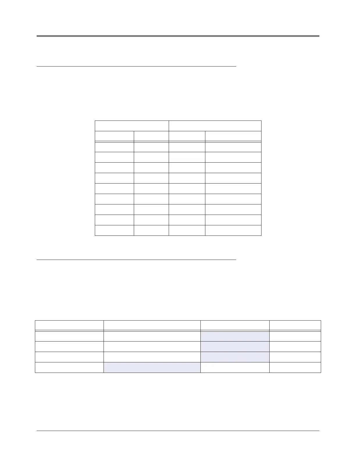
Pin layout to connect the console’s Serial Interface DB-9 connector to a 25-pin computer terminal connector are
shown in Table 1 below. These connections are standard for “AT” style modem cables.
Comm Port 2 Pin-Outs
Comm Port 2 is selectable for RS-232, RS-422, or RS-485 2-wire and 4-Wire. The Comm Port 2 communications
cable connects to Power Supply board connector J8 for RS-422 and RS-485, or to connector J9 for RS-232 use
(Figure 5 on page 11). Only one communication type can be connected to Comm Port 2 at one time. Table 2
below lists the connector and pin outs for each Comm Port 2 configuration.
Table 4. TLS2/EMC2 DB-9 Pin-Outs
Console (DB-9) Computer (DB-25)
Signal Pin Pin Signal
CD 1 8 DCD
RXD 2 2 TXD
TXD 3 3 RXD
DTR 4 20 DTR
GND 5 7 GND
DSR 6 6 DSR
RTS 7 4 RTS
CTS 8 5 CTS
N/C 9 22 Ring Indicator
Table 5. Comm Port 2 Configuration
Comm Port 2 Configuration Connector J8 (Pin Outs) Connector J9 (Pin Outs) Jumper J3 Position
RS-422 TX- (1), TX+(2), RX- (3), RX+ (4), Gnd (5)
On pins 2 and 3
RS-485, 2-Wire RXTX- (3), RXTX+ (4), Gnd (5)
On pins 1 and 2
RS-485, 4-Wire TX- (1), TX+ (2), RX- (3), RX+ (4), Gnd (5)
On pins 3 and 4
RS-232
TX (1), RX (2), Gnd (5) On pins 2 and 3