Console Installation Mounting the Console
8
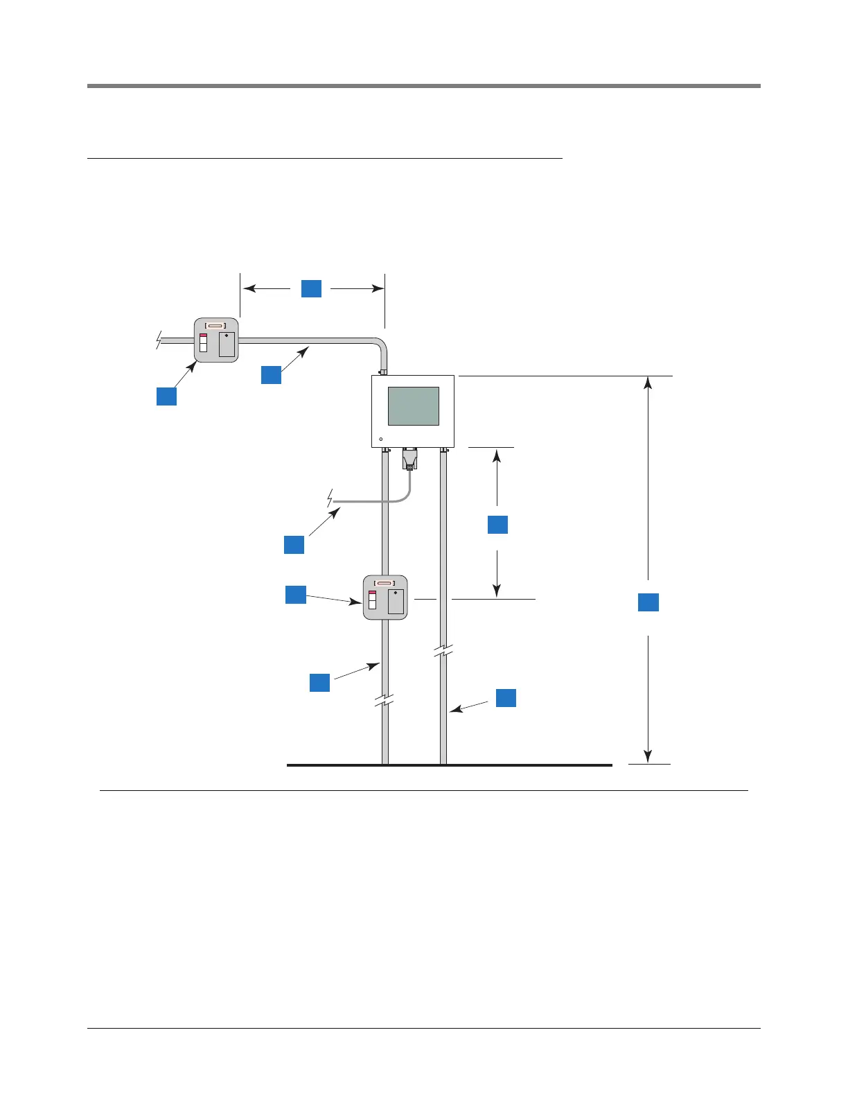
Mounting the Console
Install 1/2-inch I.P.S. (14 mm) metal conduit between the console and the power panel as shown in Figure 3 for
international installations or Figure 4 for U.S. installations.
Figure 3. Recommended Mounting of Console - International Installations
Legend for numbered boxes
1 2A neon spur
2 To an external alarm (i.e., forecourt alarm)
3 1000 mm, maximum
4 Communication cable.
5 5A neon spur
6 From an independent power supply at the distribution panel, run three 2.5 mm
2
- minimum standard color coded wires; live,
neutral, and earth, to the fused spur. Run one 4 mm
2
- minimum wire, color coded green/yellow, from the earth bus bar at the
distribution panel direct to the console location. Leave enough free cable for connection to the console.
7 1000 mm, maximum
8 Probe field cables.
9 1500 mm, maximum
consoles\tls2\mnt.eps
4
1
5
9
2
6
8
3
7