Mag Probe Installation Probe Field Wiring
28
Probe Field Wiring
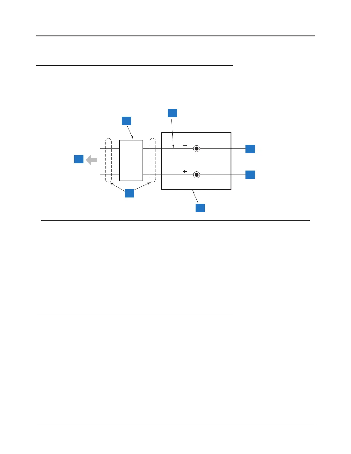
Figure 20 diagrams a typical probe field wiring connection in the junction box.
Figure 20. Probe Field Wiring Connection
Sealing Field Connections
WIRING RUN THROUGH RIGID CONDUIT
1. Pull the wires from the probe canister into the junction box. Pull two wires from the console through the seal-
off box and into the junction box.
2. Using wire nuts, connect the two wires from the probe to the two wires coming from the console. Be sure to
observe color codes or tags when making these connections.
3. Do NOT terminate drain wire at this location, ground drain wire at console only.
Legend for numbered boxes
1 To console
2 Seal off
3 Do not ground drain wire in junction box
4 Black wire (-) from probe
5 White wire (+) from probe
6 Weatherproof junction box
7 Rigid conduit
consoles/tls2/pw.eps
1
2
3
6
4
5
7