Console Installation Wiring the Console
11
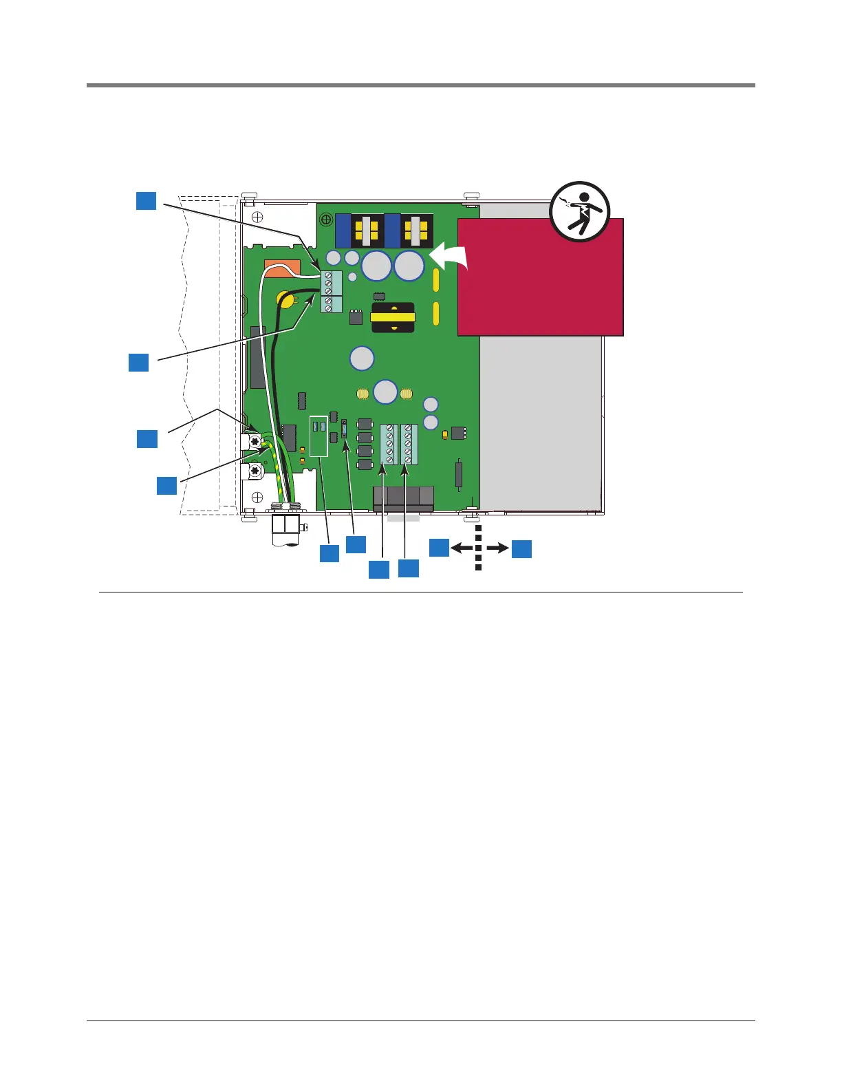
Figure 5. Wiring AC Power to the Console
Legend for numbered boxes
1 Attach neutral wire (N) to top terminal (J5).
2 Attach hot wire (L) to bottom terminal (J5).
3 Attach chassis ground wire to ground lug.
4 Attach protective earthing conductor (green and yellow) - 4 mm
2
(minimum) barrier ground wire to ground lug. (The other end
of this conductor must be connected to a “known good earth ground”).
5 Term1 (J7) and Term2 (J4) jumpers. Remove these two jumpers when using the Comm 2 port in RS-485 multidrop mode and
the console is not at the end of the network.
6 Comm 2 Port configuration jumper J3. Pin 1 is on the bottom of the 4-pin jumper. Jumper shown in the RS-422 configuration
position (on pins 2 & 3). For RS-485 2-wire configuration put jumper on pins 1 & 2. For RS-485 4-wire configuration put
jumper on pins 3 & 4.
7 Comm 2 port connector J8 - RS-422/RS-485 only (pin 1 on top).
8 Comm 2 port connector J9 - RS-232 only (pin 1 on top).
Note: Comm 2 can support either RS-232 or RS-422/ RS-485. Only one terminal connector (J8 or J9) can be installed at a
time. For Comm 2 port pin outs, see page 37.
9 Power side of console.
10 Intrinsically safe side of console (under cover).
Power Wiring Notes
• Barrier ground must be #12 AWG (4mm
2
) or larger wire.
• Use an ohmmeter to check the electrical resistance between the console’s metal case and the earthing ground
wire’s connection at the “known good earth ground”. It should read less than 1 ohm.
• Connect the power supply wires in the power panel to a separate dedicated circuit.
• Electrical rating of power input - 120 or 240 Vac, 50/60 Hz, 2 ampere maximum.
• See Figure 2 for locations of power conduit knockouts into the console. Power wiring must enter the console through
designated knockouts.
J
5
J
6
J
8
4W
J
3
2W
J4 TERM2
J7 TERM1
J
9
11
consoles/tls2/pcon.eps
1
2
3
4
9
10
6
5
7
8
WARNING!
Shock hazard. Do not
touch metal ends of
capacitors C24/C27
or the metal bands
on chokes L2/L4.
L2 L4
L2 L4
C27C24
C27C24