Introduction Control Drawing
3
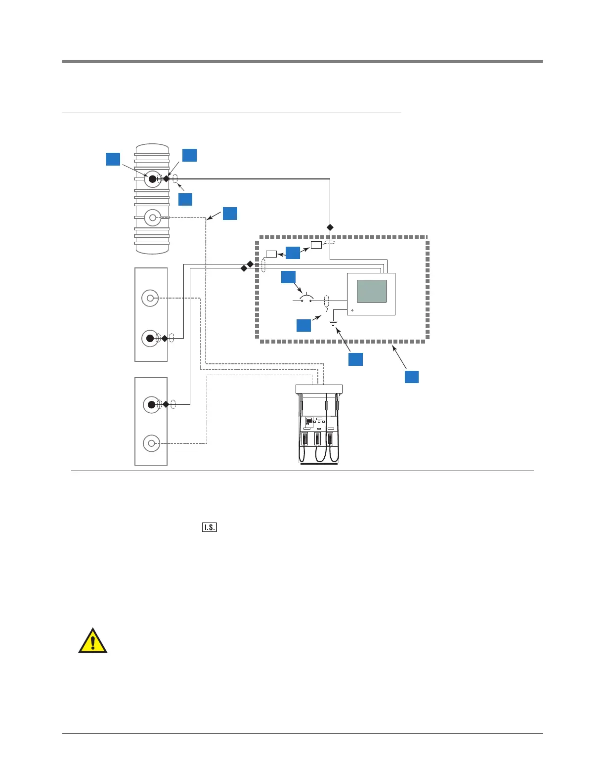
Control Drawing
Figure 1. Control Drawing - Example TLS2/EMC2 System Site Layout
Legend for numbered boxes
1 Magnetostrictive probe field wiring connection enclosed in a weatherproof junction box
2 Seal off
3 Rigid conduit
4 Product piping
5 Intrinsically safe wiring marked shall be installed in accordance with Article 504-20 of the NEC, ANSI/NFPA 70 and
enters an intrinsically safe knockout in the console
6 15 ampere circuit breaker; or fused, switched, neon indication spur
7 This conduit enters a power area knockout in the console
8 12 AWG (4mm
2
) barrier ground wire
9 Dotted line denotes isolation from hazardous area (e.g., a building).
Notes
To be installed in accordance with the National Electrical Code, NFPA 70 and the Code for Motor Fuel Dispensing
Facilities and Repair Garages (NFPA 30A), or other local codes such as the CEC, Canadian Electrical Code.
Conduit requirements are dependent on local electrical regulations. For probe-to-console wiring, shielded cable is
required regardless of conduit requirements.
WARNING: Substitution of components may impair intrinsic safety.
Circuitry within the console barrier forms an intrinsically safe, energy-limited system. This system makes console
probes safe for use in a Class I, Group D hazardous locations. Console probe wiring is intrinsically safe only when
connected to Veeder-Root/Gilbarco Consoles. Reference Console Form Number 8560 and Probe Form Numbers
8462, 8463, 8468, and 8473.
MP
MP
Non-Hazardous
Area
120/240 Vac
15 A
consoles/tls2/newsysdia.eps
Hazardous Area
PA
MP
1
2
3
4
6
7
8
9
I.S.
I.S.
5