Mag Probe Installation Probe Wiring Precautions
31
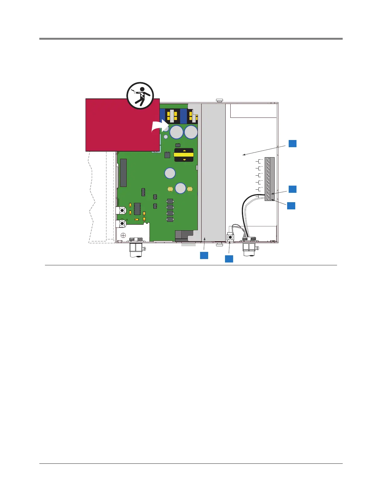
Figure 22. Connecting Probe Wiring to Console
Legend for numbered boxes
1 Circuit Directory label
2 Black wire from probe 1 connects to (-) terminal
3 White wire from probe 1 connects to (+) terminal
4 Attach probe 1 cable shield and /or drain wire to ground lug
5 Intrinsically safe wiring cover (shown swung open to left)
J4
J5
AVERTISSEMENT
LA SUBSTITUTION DE COMPOSANTS
PEUT COMPROMETTRE LA SECURITE
INTRINSEQUE.
consoles/tls2/pbwr.eps
PROBE 6
+
PROBE 5
+
+
PROBE 4
+
PROBE 3
+
PROBE 2
+
PROBE 1
WARNING
SUBSTITUTION OF COMPONENTS
MAY IMPAIR INTRINSIC SAFETY.
NO REPAIRS SHOULD BE ATTEMPTED.
REFER SERVICING TO QUALIFIED
PERSONNEL ONLY.
4
2
3
5
1
WARNING!
Shock hazard. Do not
touch metal ends of
capacitors C24/C27
or the metal bands
on chokes L2/L4.
C24 C27
C24 C27
L2 L4
L2 L4