Communications Surge Protection for Communication Devices
36
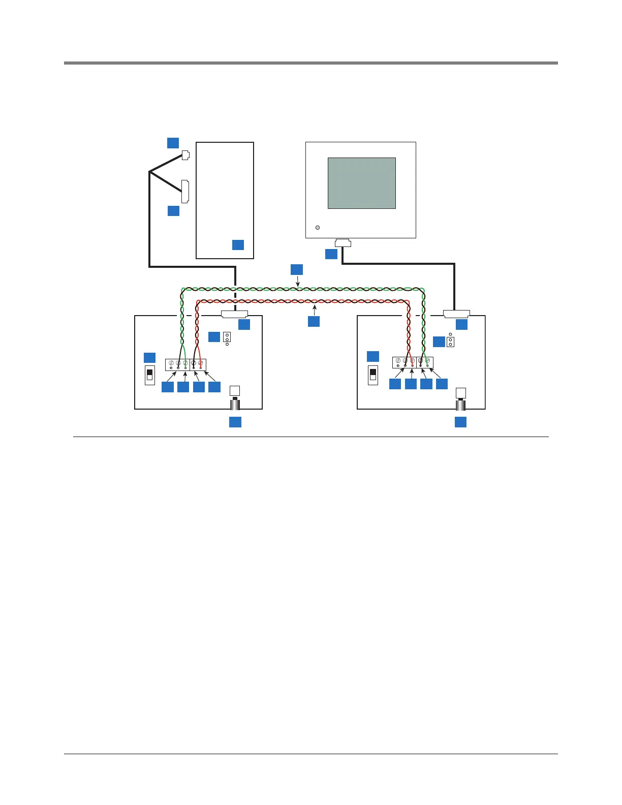
Figure 26. Example of Console Connected to a Remote Device Via MDE800A Short-Haul Modems
Legend for numbered boxes
1 DB9 connector or (2) DB25 connector - depends on availability
3 Personal Computer
4 Twisted pair 24 or 26 AWG (0.2 mm
2
) cable
5 DB9 connector on bottom of console
6 DB25 connector on rear of short haul modem
7 RTS/DTR Control jumper (in modem) - select DIS position
8 Front panel switch - select Normal position
9 RX+ terminal - attach color 2 wire of twisted pair (4) to this terminal (in modem)
10 RX- terminal - attach color 1 wire of twisted pair (4) to this terminal
11 TX+ terminal - attach color 2 wire of twisted pair (14) to this terminal
12 TX- terminal - attach color 1 wire of twisted pair (14) to this terminal
13 DCE/DTE switch (in modem) - select DCE position
14 Twisted pair 24 or 26 AWG (0.2 mm2) cable
15 RTS/DTR Control jumper (in modem) - select EN position
16 Attach color 2 wire of twisted pair (14) to this terminal
17 Attach color 1 wire of twisted pair (14) to this terminal
18 Attach color 2 wire of twisted pair (4) to this terminal
19 Attach color 1 wire of twisted pair (4) to this terminal
consoles\tls2\shm.eps
4
19
4
18
4
17
4
16
4
12
4
11
4
10
4
9
4
13
4
7
4
6
4
6
4
5
4
4
4
14
4
2
4
3
4
1
4
8
4
13
4
8
4
15