30
7 Setup
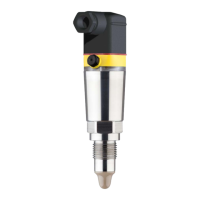
VEGAPOINT 21 • Transistor (NPN/PNP)
56623-EN-210210
•
Peak values, electronic temperature
•
Pointer function measuring cell temperature
•
Pointer function resonance frequency
In this window you can also reset each of the three pointers individu-
ally.
In this menu item you can retrieve the current measured values of the
device.
Measured values
Here you can view the current coverage status of the device (covered/
uncovered).
Additional measured values
Hereyoucanndadditionalmeasuredvaluesofthedevice.
•
Electronic temperature (°C/°F)
•
Measuring cell temperature (°C/°F)
•
Resonance frequency (%)
Outputs
Here you can retrieve the current switching status of the output
(closed/open).
•
Output
In this menu item you can simulate the function of the two switching
outputs separately.
Note:
Make sure the connected downstream devices are activated during
the simulation.
First select the desired switching output and start the simulation.
Then select the desired switching state.
•
Open
•
Closed
Click on the button "Accept simulation value".
The sensor now switches to the desired simulation switching status.
Duringsimulation,theLEDdisplayashesinthecolourofthese-
lected switching status.
A simulation of the fault status is not possible.
To cancel the simulation, click on "Terminate simulation".
Note:
Without manual deactivation, the sensor terminates the simulation
automatically after 60 minutes.
In this menu item you can see the impedance curve of the device.
The impedance curve gives information about the switching behav-
iour of the sensor.
Measured values
Simulation
Impedance curve