12
4 Mounting
VEGAPULS 21 • Two-wire 4 … 20 mA/HART
58351-EN-191014
4.2 Mounting instructions
Radar sensors for level measurement emit electromagnetic waves.
The polarization is the direction of the electrical component of these
waves.
The polarization direction is marked on the housing, see following
drawing:
1
Fig. 5: Position of the polarisation
1 Marking of the polarisation
Note:
When the housing is rotated, the direction of polarization changes
andhencetheinuenceofthefalseechoonthemeasuredvalue.
Please keep this in mind when mounting or making changes later.
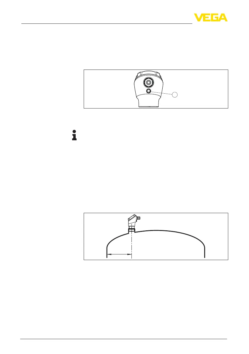
When mounting the sensor, keep a distance of at least 200 mm
(7.874 in) from the vessel wall. If the sensor is installed in the center
of dished or round vessel tops, multiple echoes can arise. However,
these can be suppressed by an appropriate adjustment (see chapter
"Set up").
If you cannot maintain this distance, you should carry out a false
signal suppression during setup. This applies particularly if buildup on
the vessel wall is expected. In such cases, we recommend repeating
the false signal suppression at a later date with existing buildup.
> 200 mm
(7.87
")
Fig. 6: Mounting of the radar sensor on round vessel tops
In vessels with conical bottom it can be advantageous to mount the
sensor in the centre of the vessel, as measurement is then possible
down to the bottom.
Polarisation
Installation position