EXS
User Manual 10H52260UM60 - Rev. 1 - 10/2017 95
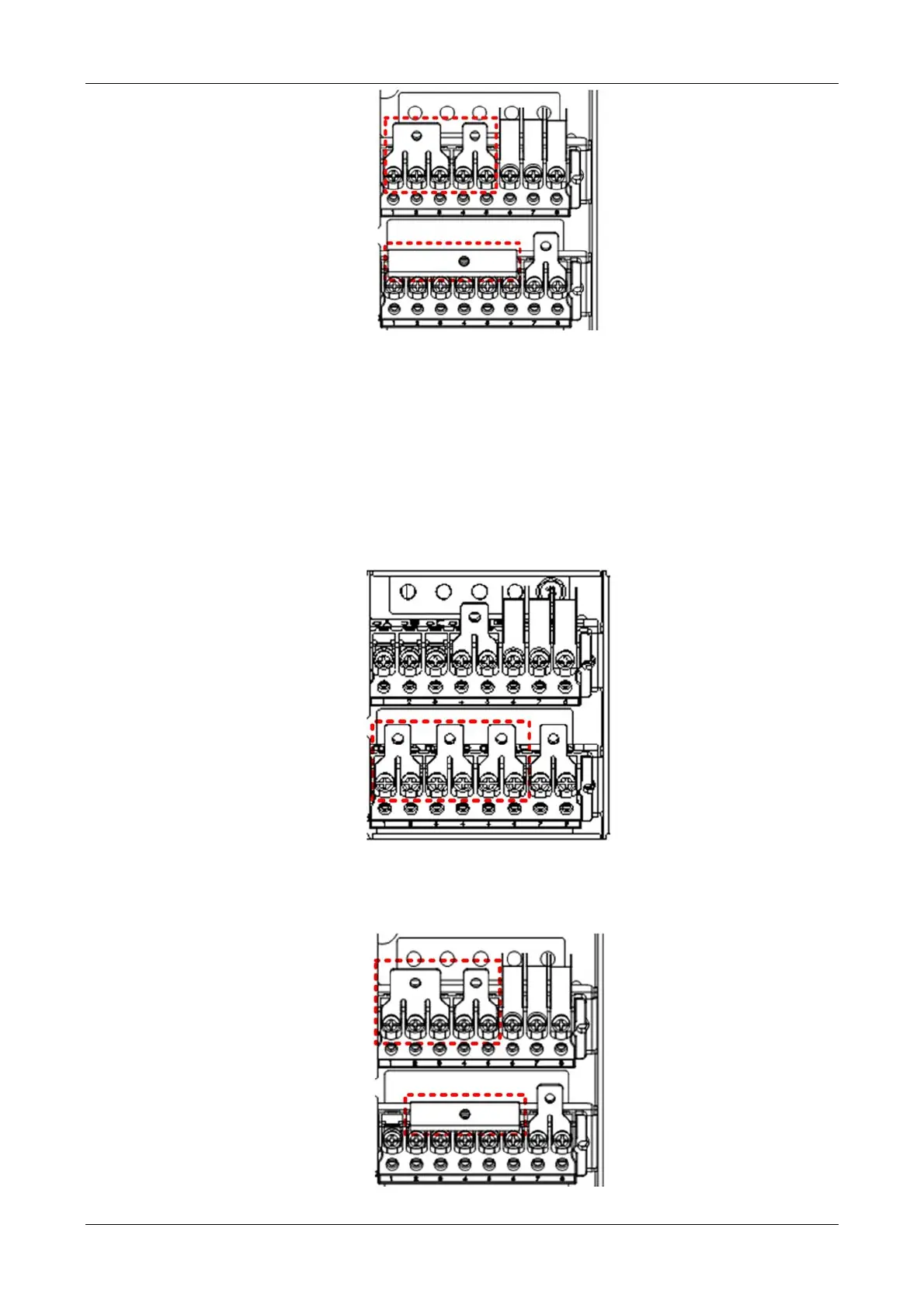
Figure 8-16 3-in 1-out, common input configuration (2)
c) Connect the phase A input cables to the input copper shorting bars, and connect the input N line to the neutral
terminal 'N' in the cabinet. Connect the phase B and phase C cables respectively to terminals mB and mC, and then
connect the I/O earth cables to the PE terminal in the cabinet.
d) Connect the output cable to the output copper shorting bar, and the output N line to the output N copper
shorting bar.
e) Connect the battery positive, battery N and battery negative respectively to the Bat+, N, Bat- terminals.
2. 3-in 1-out, split bypass configuration
a)
Remove the three copper shorting bars from the rectifier input terminals mA, mB and mC, see Figure 8-17.
Figure 8-17 3-in 1-out, split bypass configuration (1)
b) Install the bypass input copper shorting bars to terminals (bA, bB, bC), and use the output shorting copper bars
to connect the output terminals (oA, oB, oC) together. See Figure 8-18.
Figure 8-18 3-in 1-out, split bypass configuration (2)