Vertiv | Liebert® DM | User Manual 97
System Operation and Maintenance
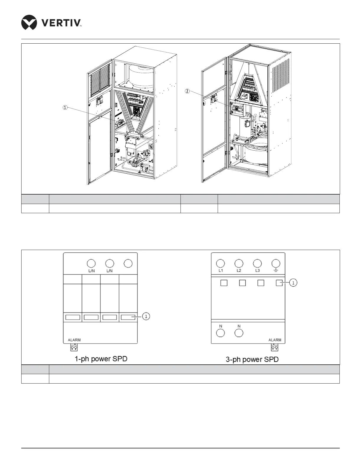
DM 22 kW/ 27 kW Upflow Unit DM 22 kW/27 kW Downflow Unit
No. Description No. Description
1 Power SPD 2 Power SPD
Figure 7-8 Power SPD Location (22 kW and 27 kW)
There are four status indicators on the power SPD, as shown in Figure 7-9. The status indicator is green during normal
operation, and turns red when the SPD fails.
No. Description
1 Status Indicator (4 PCS)
Figure 7-9 Location of Status Indicators of Power SPD
The power SPD does not need special maintenance. It needs regular check for non-loosening and normal status indication.
If any one of the following phenomena appears, the power SPD has failed and it needs to be replaced immediately:
1. Any indicator of the power SPD turns red.
2. The customer alarm 2 is registered, refer Section 3.5.1, Connecting Control Terminal in SPD (custom 2 terminal).
 Loading...


