Vertiv | Liebert® DM | User Manual 20
Mechanical Installation
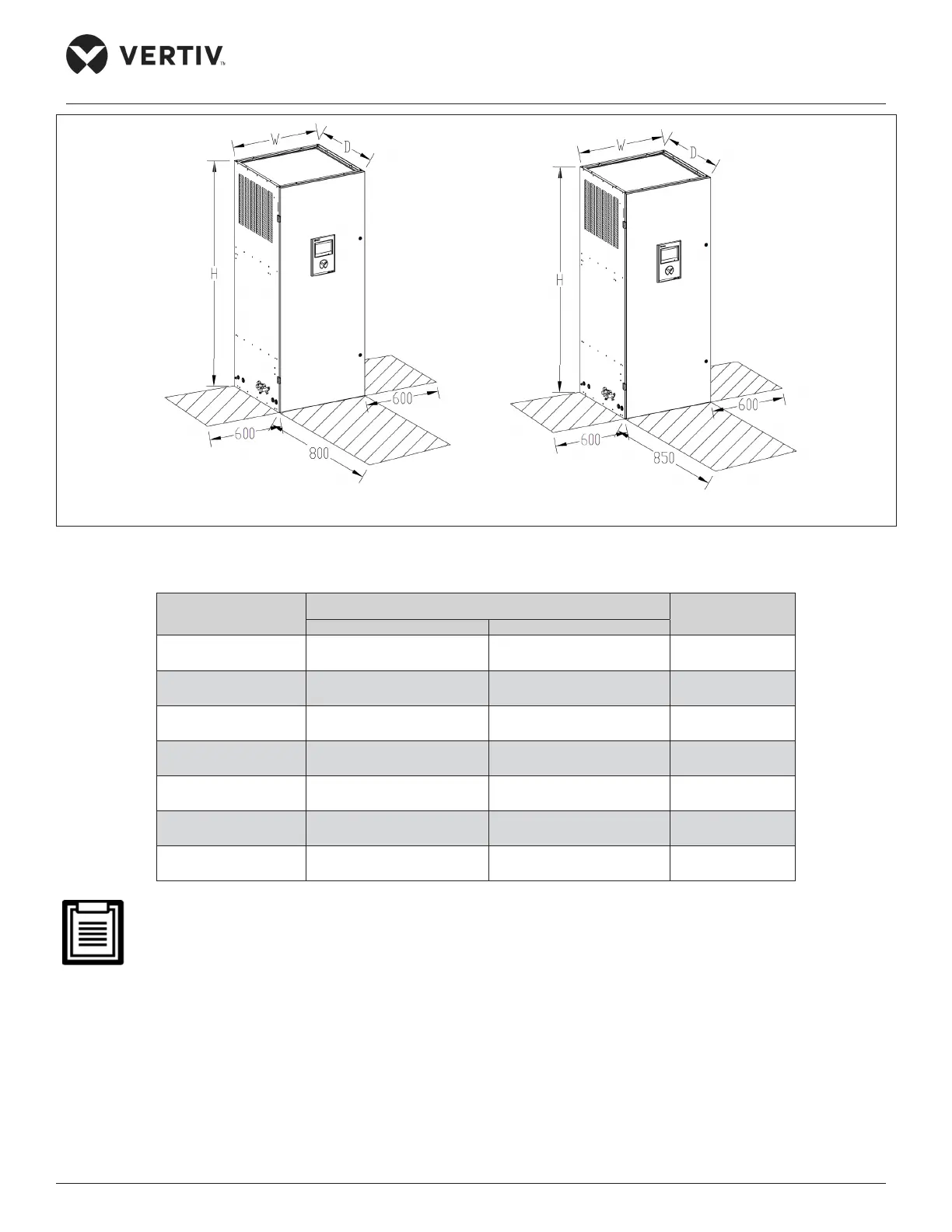
DME22M*0FA*1 (Downflow Unit) DME27M*1FA1 (Downflow Unit)
Figure 2-6 Vertiv™ Liebert® DM Downflow Indoor Unit (22 kW and 27 kW)
Table 2-1 Mechanical Parameters of Indoor Unit
Model
Dimensions (W × D × H)
Operational
Weight (kg)
mm inch
DME07M**UA1 510x385x1850 20.08x15.16x72.83 85
DME12M**UA1 600x500x1975 23.62x19.69x77.76 125
DME17M*0UA1 750x650x1975 29.53x25.59x77.76’ 230
DME22M*0UA1 800x765x1975 31.5x30.1x77.8 253
DME22M*0FA1 800x765x1975 31.5x30.1x77.8 284
DME27M*1UA1 850x835x1975 33.5x32.9x77.8 283
DME27M*1FA1 850x835x1975 33.5x32.9x77.8 280
• The maintenance space required for the upflow and downflow indoor units are shown in Figure 2-4,
Figure 2-5 and Figure 2-6 respectively.
• The unit equipped with a heater should be kept at least 150 mm away from the combustible substance.
While testing the unit, maintain the external static pressure below 100 Pa before the air volume
becomes too low and the heater becomes too hot.
 Loading...


