Vertiv | Liebert® DM | User Manual 70
Microprocessor Controller
Table 5-3 describes dierent control modes of the display.
Table 5-3 Control Mode Diagram Description
No. Description
1 The color in the circle is red, gray and green. See Table 5-4 for details.
2 Measured current return air temperature value
3
Humidity setting value, according to the range of humidity setting value, clockwise rotation
changes between 30° to 150° of polar coordinate angles. If the humidity setting value is minimum
value, the humidity setting value is 30° in polar coordinates. When the humidity setting value is the
maximum value, the humidity setting value is 150° in polar coordinates.
4 Humidity control, default is return air humidity control, display RETURN.
5
indicates humidity.
6
indicates temperature.
7 Temperature control, default is return air temperature control, display RETURN.
8 Measured current return air humidity value.
9
The temperature setting value, according to the range of the temperature setting value,
counterclockwise rotation changes between the 30° to 150° of polar coordinate angles , if the
temperature setting value is the maximum value, the temperature setting value is at the polar
coordinate 30°. When the temperature setting value is the minimum value, the temperature setting
value is 150° in polar coordinates.
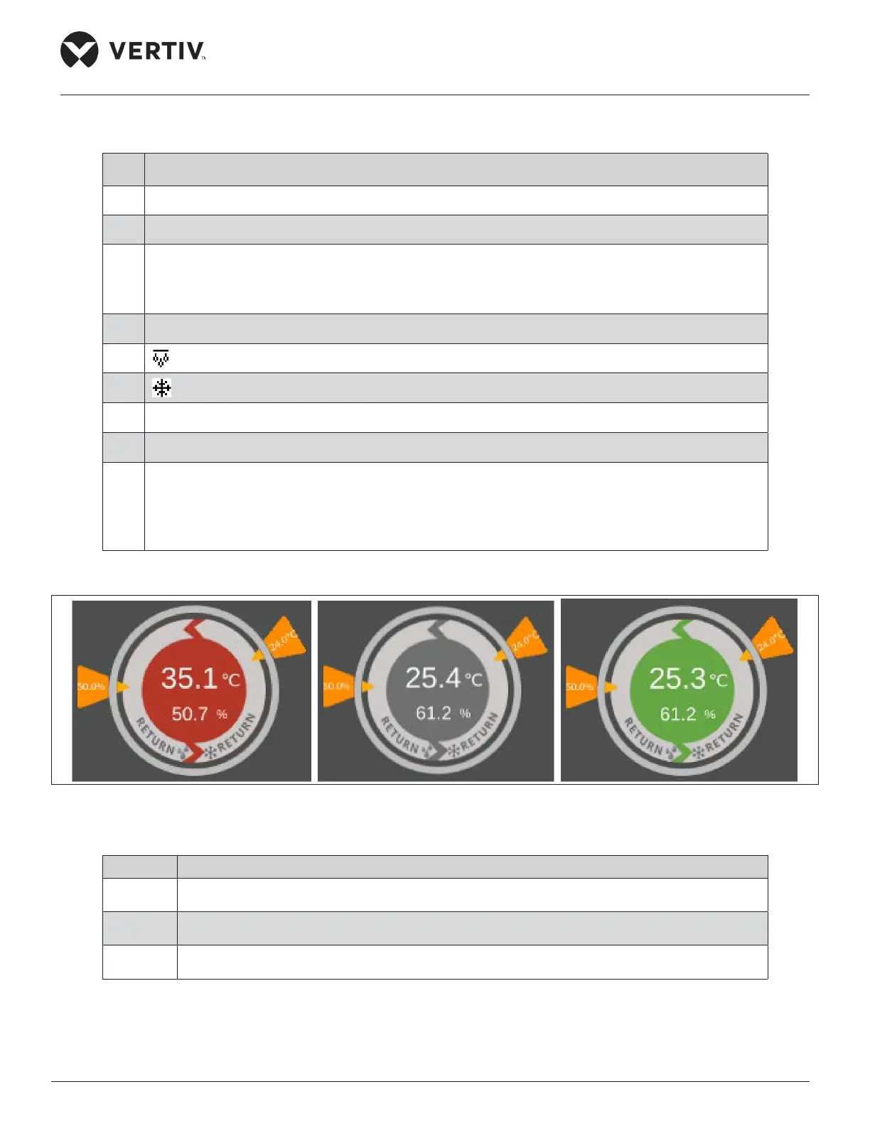
There are three types of unit status colors in main interface, as shown in Figure 5-4 below:
Figure 5-4 Unit Status Colors
Table 5-4 Description of Unit Status Colors
Status Description of System Status
Red The power-on status sensor data is not in the normal range or is invalid.
Gray Power- o state
Green The power-on status is within the normal range
 Loading...


