Vertiv | Liebert® DM | User Manual 84
Outdoor Fan Speed Controller (Only for 22 kW/27 kW)
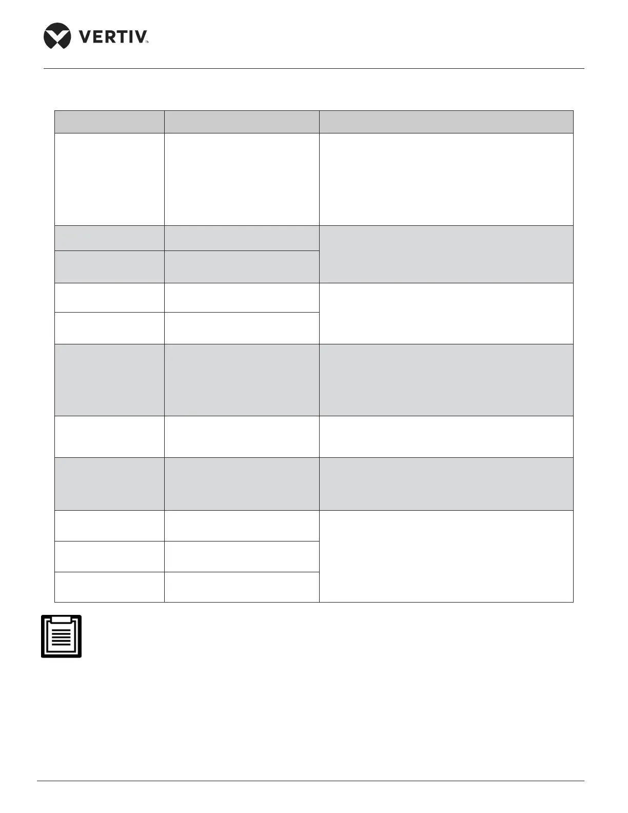
The description of each speed controller board terminal is given in Table 6-1
Table 6-1 Description of Terminals
Terminal/Terminals Description Pin Definition
J1 AC input and output terminal
• PE: Protected Earth.
• L1, L2, L3: Three-phase AC input.
• U, V, W: Three-phase AC output, connected to the
fan power supply terminal.
• The intermediate terminal pins without
identification are reserved.
J3 (HP1)
Voltage type pressure sensor 1
connection terminal
• Pin 1: 5 V positive power supply terminal.
• Pin 2: pressure voltage signal 0.5 V to 4.5 V input.
• Pin 3: 5 V voltage negative terminal.
J4 (HP2)
Voltage type pressure sensor 2
connection terminal (backup)
J15 (HP1)
Current type pressure sensor 1
connection terminal
• Pin 1: 12 V positive power supply terminal.
• Pin 2: 4 mA to 20 mA input for pressure and
current signals.
J14(HP2)
Current type pressure sensor 2
connection terminal (backup)
J17, J18
Short circuit jumper for current
type pressure sensor
• This type of short-circuit jumper must be installed
with a jumper cap when using a current-type
pressure sensor.
• The short circuit jumper must be kept open when
using a voltage type pressure sensor.
J5 (Out Temp)
Ambient temperature sensor
input terminal (backup)
• Pin 1: Temperature signal input.
• Pin 2: Signal reference ground.
J11 (RS232)
Serial communication interface
(used during maintenance)
• Pin 1: Communication ground.
• Pin 2: Communication receiving end.
• Pin 3: Communication sender.
J7 (Fan1Sta)
Fan 1 over temperature
detection terminal
• Pin 1: 19 V AC signal output.
• Pin 2: 19 V AC signal return.
J10 (Fan2Sta)
Fan 2 over temperature
detection terminal
J6 (CompSta)
Compressor status detection
terminal
J8 (SCRTemp) in Figure 6-1 is the unit interface on the fan speed controller board, not open to users.
 Loading...


