Vertiv™ | Liebert® DM | User Manual 50
Electrical Installation
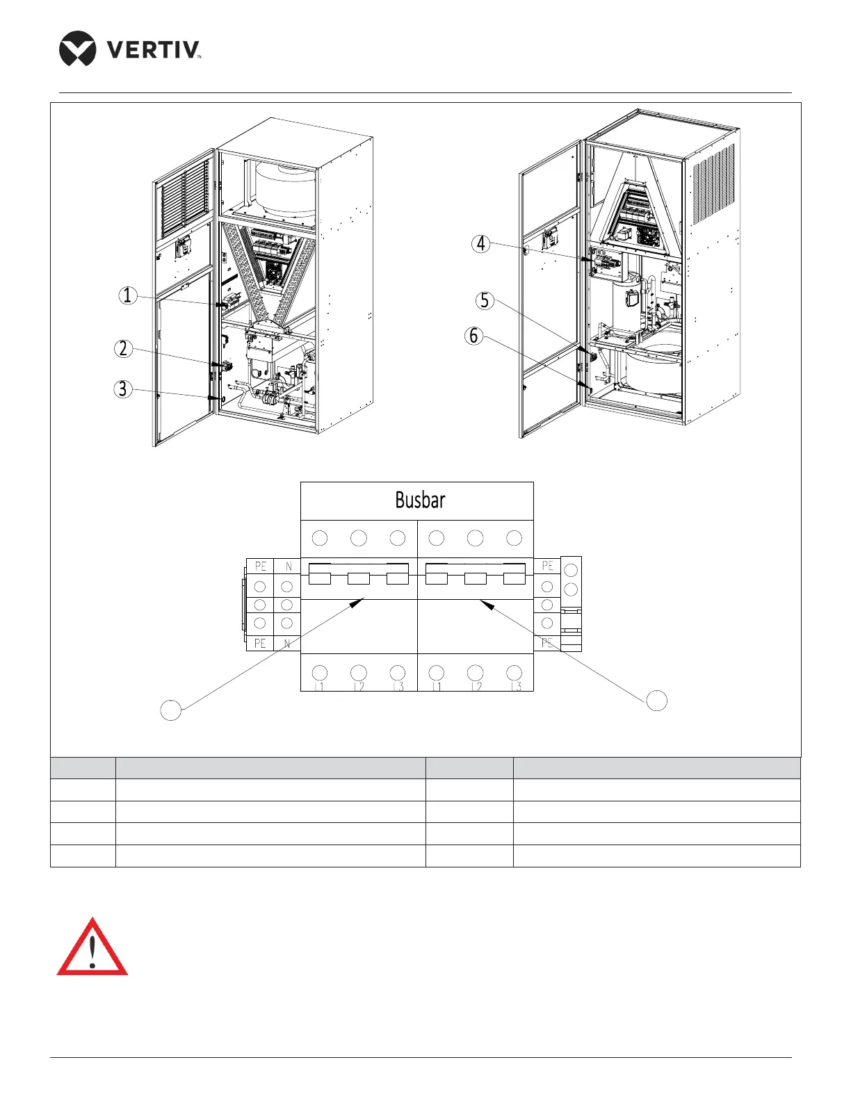
Upflow Unit Downflow Unit
Enlarge view of Power Input Terminal for DM 22 kW/27 kW
No. Description No. Description
1 Power input terminal 5 Cable clamp
2 Cable clamp 6 Cable hole
3 Cable hole 7 Indoor unit switch
4 Power input terminal 8 Outdoor unit switch
Figure 3-3 Indoor Unit Power Cabling Diagram (22 kW/ 27 kW)
Cut o the power supply to the unit prior to the maintenance, because the unit contains high voltage.
7
8