Vertiv™ | Liebert® DM | User Manual 56
Electrical Installation
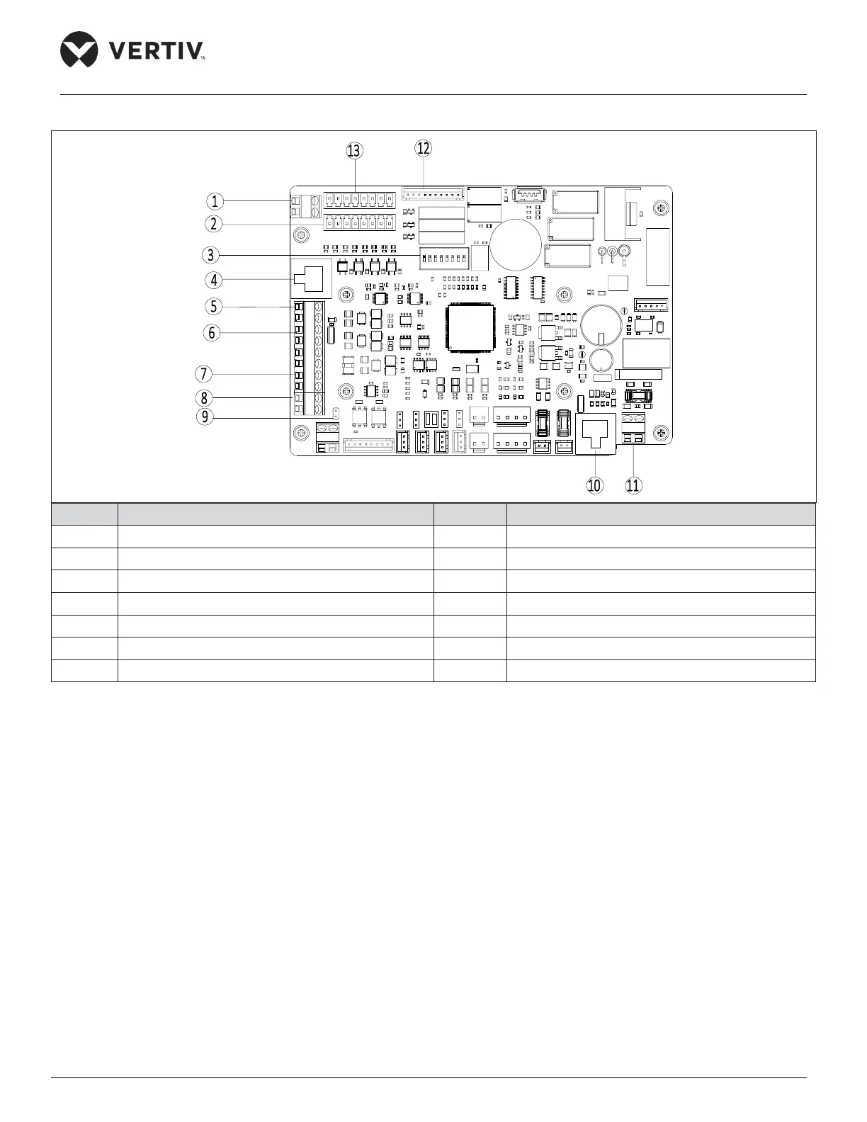
The control terminal arrangement is shown in Figure 3-10.
No. Description No. Description
1 J31 DI input power 8 J20 teamwork control
2 J21 input of high pressure switch and so on 9 J27 teamwork control jumper
3 SW3 teamwork control DIP switch address 10 J34 temperature and humidity detection board
4 J38 Energy-saving Card 11 J13 single broad power input
5 J39 display data cable 12 J28 output of electrical heater and so on
6 J12 SIC power 13 J19 input of remote On/O and so on
7 J14 monitoring
Figure 3-10 Control Terminal Arrangement on PCB