Vertiv | Liebert® DM | User Manual 78
Microprocessor Controller
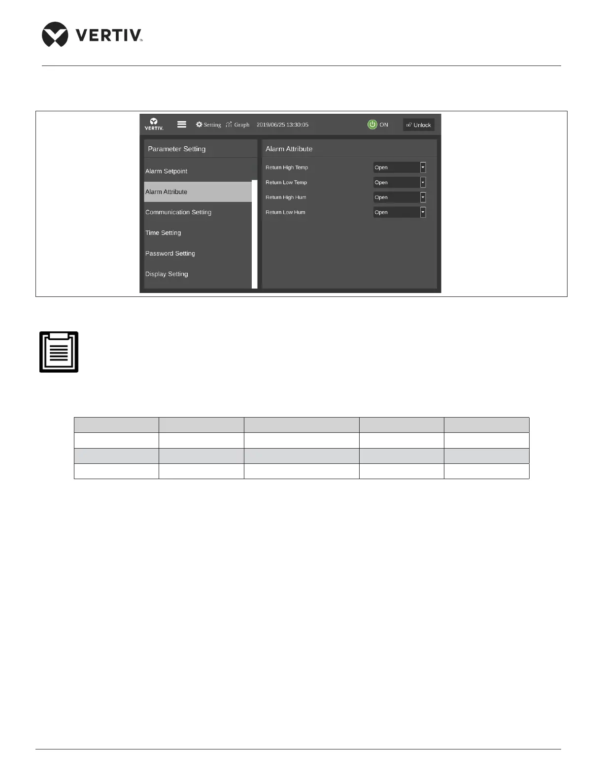
• Alarm Attribute
Figure 5-16 shows the Alarm Attribute menu interface.
Figure 5-16 Alarm Attribute
• The alarm settings are saved for permanent memory. It is not recommended to change the default value
of the alarm setpoint and turn o the alarm properties. The alarm output logic is shown in Table 5-7. If it is
necessary, please operate under the guidance of a trained professional.
Table 5-7 Alarm Output Logic
Set Value Alarm History Alarm Status record Alarm Sound Alarm Prompt
Enabled Yes Yes Yes Yes
Ceases Yes Yes No No
Disabled No No No No
• Communication Setting
The Communication Setting menu interface is shown in Figure 5-17.