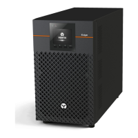
Vertiv | Liebert® EDGE | Installer/User Guide 5
Table 1-2 EDGE Rear-panel Descriptions
ITEM DESCRIPTION
1 Grounding screw
2 USB communication port
3 Programmable receptacles
4 Non-programmable receptacles
5 SNMP IntelliSlot port
6 Emergency Power O (EPO) connector
7 7 Input circuit breaker
8 AC input
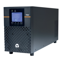
1.3. Front Panel
NOTE: For detailed descriptions of the LCD display. See Controls on page 16.
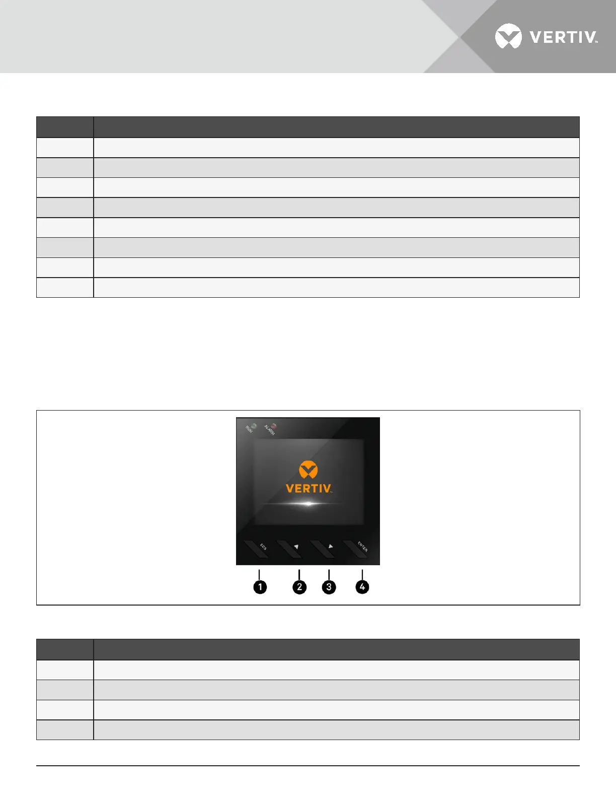
Figure 1-2 Controls and Display on 2U and MT Models
ITEM DESCRIPTION
1
ESC/MUTE button. See Controls on page 16, for details.
2
UP/RIGHT button. See Controls on page 16, for details.
3
DOWN/LEFT button. See Controls on page 16, for details.
4
ENTER/[POWER SYMBOL HERE] button. See Controls on page 16, for details.
 Loading...