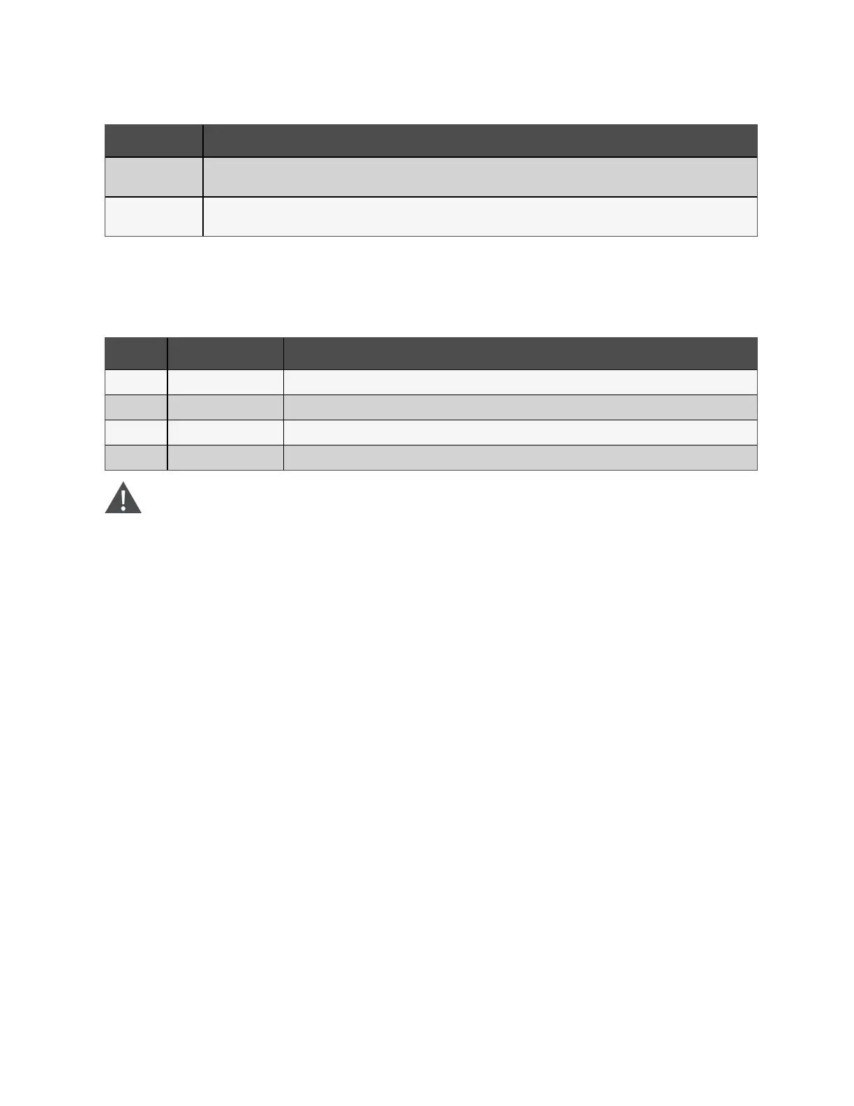
Card Description
Vertiv™ Liebert®
IS-485EXI Card
Communicates with Vertiv™ SiteScan monitoring system.
Vertiv™ Liebert®
IS-RELAY Card
Provides dry contact alarm information, including signals for: On Battery, On Bypass, Low Battery, Summary Alarm, UPS Fault and
On UPS for communication to a remote monitoring system or network connected Vertiv or third party shut down software.
Table 3.8 Liebert® intelliSlot™ Communication Cards (continued)
3.4.2 REPO connection
The Table 3.9 below, describes the pin out of the REPO port, J14, used for N.O. or N.C. connection.
J14 Pin No. Pin Name Description
2 REPO Coil N.C. Normally Closed circuit, EPO is activated when Pin 2–Pin 4 is opened.
4 +12 VDC REPO power supply, 12 VDC, 100 mA.
6 +12 VDC REPO power supply, 12 VDC, 100 mA.
8 REPO Coil N.O. Normally Open circuit, EPO is activated when Pin 6–Pin 8 is closed.
Table 3.9 REPO Port (J14) Pin Descriptions
WARNING! Risk of electrical shock. Can cause equipment damage, injury and death.
The EPO action of the UPS will shutdown the rectifier, inverter, and static bypass, but it does not disconnect
input power to the UPS. To electrically isolate the UPS, an interface with the external REPO circuit must be
field supplied to allow disconnecting the UPS input feeder breaker to remove all sources of power to the UPS
and connected equipment to comply with national and local wiring codes and regulations.
The Figure 2.2 on page7, shows the location of the REPO connection inside the UPS front panel. Figure 3.5 on the next page,
shows the connection details.
If a REPOconnection is not required for the UPS, the factory installed jumper between Pin2 and Pin4 must remain installed
for the UPS to operate.
NOTE: The terminal block wire range is 18AWG to 22AWG (0.82mm
2
to 0.33mm
2
), and we recommend using 18 AWG
copper, shielded, and signal cable.If the REPO will trip an external, electronically controlled circuit breaker, you must
reset the breaker before starting the UPS after the REPO is activated.
NOTE: We recommend that you route the wiring for the REPO connection from the rear of the UPS through the built in
wiring pass through to connect to the REPO port. See Figure 2.2 on page7, for the location of the pass through.
3 Installation and Commissioning Proprietary and Confidential ©2023 Vertiv Group Corp. 27
Vertiv™ Liebert® EXS Installer/User Guide