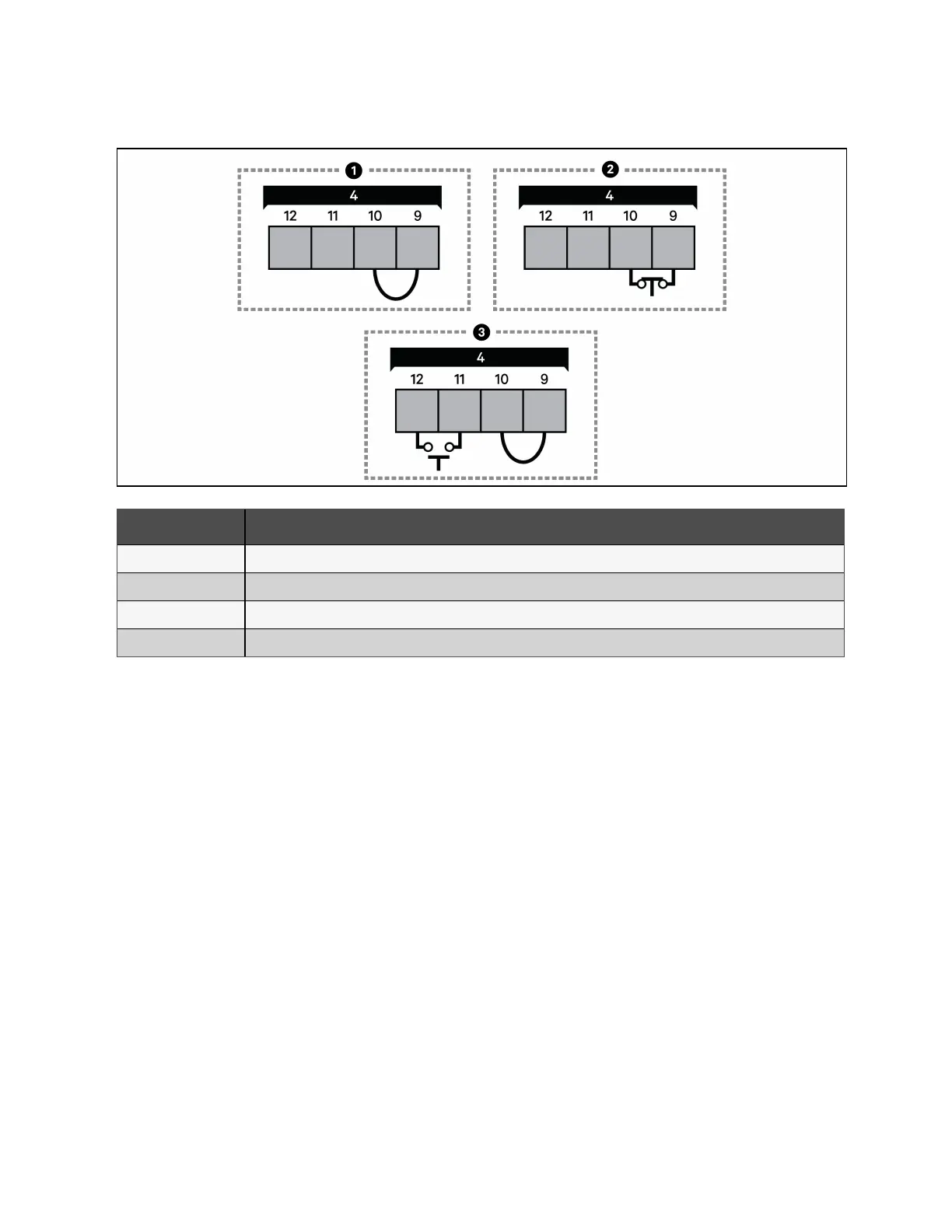
Figure 3.5 REPO Connection on J14
Item Description
1 No REPOconnection—factory supplied jumper must remain installed.
2 Normally closed (N.C.) connection—remove factory supplied jumper and wire pins 2 and 4 to a remote switch.
3 Normally open (N.O.)connection—factory supplied jumper must remain installed.
4 Port J14. See Table 3.9 on the previous page, for the pinout details.
3.4.3 Connecting USB communication cables
The UPS includes a standard, USB Type-A port is provided for service and troubleshooting by Vertiv's service technicians.
3.4.4 Dry contact input and output connections
The UPS contains 5 sets of configurable input contacts and 2 sets of configurable output contacts. Figure 2.2 on page7,
shows the dry contact location inside the front panel, and Figure 3.6 on the facing page, shows the connection details. Table
3.10 on the facing page, and Table 3.11 on the facing page, describe the pin out designations, allowable configuration
selections, and factory details.
NOTE: The terminal block wire range is 18AWG to 22AWG (0.82mm
2
to 0.33mm
2
), and we recommend using 18 AWG
copper, shielded, and signal cable.
All input dry contact ratings are 12 VDC, 20 mA maximum. The output dry contact rating is 24 VDC, 0.5 A maximum.
The inputs expect the external dry contact to be N.O. and to close in order to trigger the alarm/action. The output dry
contacts are N.O. and close in order to trigger the alarm/action.
NOTE: We recommend that you route the cables for the dry contacts from the rear of the UPS through the built-in
wiring channel to the dry contact port connections. See Figure 2.2 on page7, for the location of the pass through.
28 Proprietary and Confidential ©2023 Vertiv Group Corp. 3 Installation and Commissioning
Vertiv™ Liebert® EXS Installer/User Guide