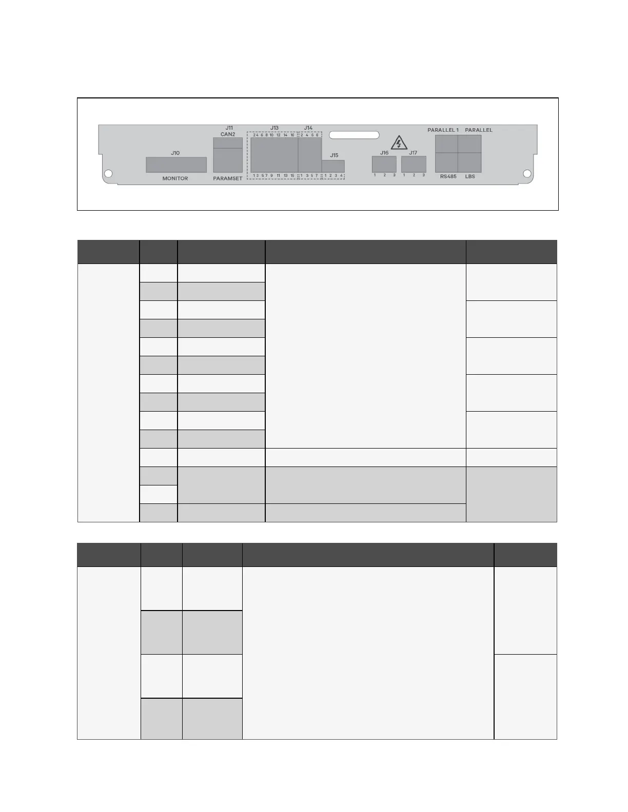
Figure 3.6 Dry Contact Connections
Connector ID Pin No. Pin Name Description Default
J13
1 Input #1 N.O.
General purpose inputs that may be configured for any of the
following:
• On Generator
• Transfer to Inverter Inhibit
• External MIB Status
• External MBB Status
• Module Output Breaker Status
• Battery Ground Fault Detected
• Charger Shutdown
• ECO Mode Inhibit
• Start Battery Maintenance Self Test
• Stop Battery Maintenance Self Test
• Alarm Cleared
External MIB Status
3 Input #1 Gnd
5 Input #2 N.O.
Module Output Breaker
Status
7 Input #2 Gnd
9 Input #3 N.O.
External MBB Status
11 Input #3 Gnd
13 Input #4 N.O.
On Generator
15 Input #4 Gnd
2 Input #5 N.O.
Transfer to Inverter Inhibit
4 Input #5 Gnd
6-8-10 RESERVED
12
Internal Battery Temp
Sensor
Internal battery temperature sensor inputs
N/A14
16 Temp Gnd Internal battery temperature sensor gnd
Table 3.10 Input Dry Contact Details
Connector ID Pin No. Pin Name Description Default
J14
1 Output #1 N.O.
General purpose outputs that may be configured for any of the following:
• System Alarm (Summary)
• On Battery
• Low Battery
• UPS Fault, On Bypass
• On UPS
• REPO
• Main Input Abnormal
• On Maintenance Bypass
• Load Shed Signal 1
• Load Shed Signal 2
• Internal MBB Closed
On Battery
3 Output #1 Gnd
5 Output #2 N.O.
Summary Alarm
7 Output #2 Gnd
Table 3.11 Output Dry Contact Details
3 Installation and Commissioning Proprietary and Confidential ©2023 Vertiv Group Corp. 29
Vertiv™ Liebert® EXS Installer/User Guide