6.3.2 Cabinet installation
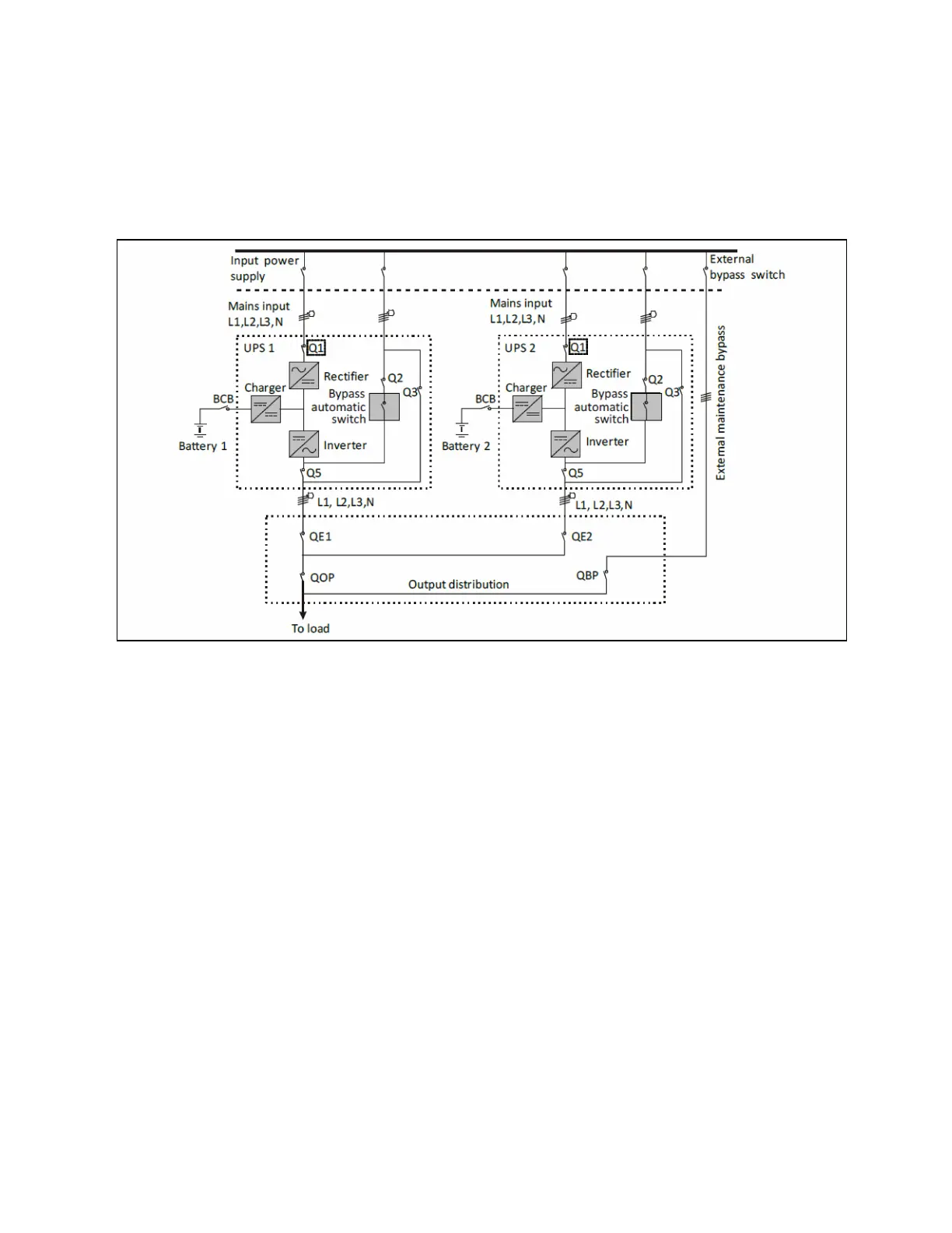
Place the UPS modules side by side and interconnect as shown in Figure 6.1 below. The output distribution mode (QE1 and
QE2 must be configured) shown in Figure 6.1 below is recommended to facilitate maintenance and system testing.
Figure 6.1 Typical Parallel System (with Common Input, Separate Batteries and Output)
6.3.3 Power cables
The power cable wiring is similar to that of the UPS module.
The bypass and rectifier input supplies must use the same neutral line input terminal. If the input has a current leakage
protective device, the current leakage protective device must be fitted upstream of the neutral line input terminal.
NOTE: The power cables of each UPS module (including the bypass input cables and UPS output cables) should be of
the same length and specifications to facilitate load sharing.
NOTE: The UPS adopts common input configuration and split bypass configuration. If the mains input and bypass
input come from two different transformers, then these two transformers should share one grounding grid.
6.3.4 Parallel cables
Shielded and double insulated parallel cables available in lengths of 5 m, 10 m, and 15 m must be interconnected between the
UPS modules in a ring configuration, as shown in Figure 6.2 on the facing page. Connect a single module parallel cable from its
PARALLEL1 port to the PARALLEL2 port of another module. Repeat this step for all the other parallel cables.
The ring connection ensures the reliability of the control of the parallel system. Make sure that the cables are securely
connected before starting the system.
48 Proprietary and Confidential ©2023 Vertiv Group Corp. 6 Parallel System and LBS System
Vertiv™ Liebert® EXS Installer/User Guide