4 Operation and Display Panel
The operation/display panel includes LED indicators, function keys, and an LCDinterface to configure and control UPS
operation.
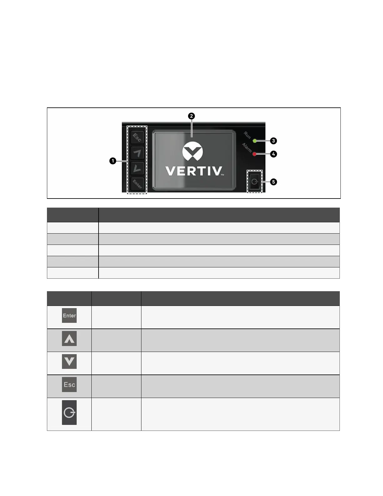
Figure 4.1 UPS Front Panel Display
Item Description
1 Menu keys, see Table 4.1 below.
2 LCD panel
3 Run indicator LED. See LED Indicators on the next page.
4 Alarm indicator LED. See LED Indicators on the next page.
5 Power button. See Table 4.1 below.
Button Function Description
Enter Confirm or enter selection.
Up Move to previous page, increase value, and move left.
Down Move to next page, decrease value, and move right.
Escape Go back.
Power Power on the UPS, power off the UPS, and transfer to bypass mode.
Table 4.1 Display Panel Button Functions and Descriptions
4 Operation and Display Panel Proprietary and Confidential ©2023 Vertiv Group Corp. 31
Vertiv™ Liebert® EXS Installer/User Guide