3.1 Planning Dimensions
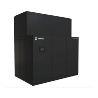
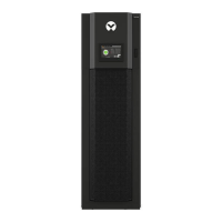
The condenser dimensions are described in the submittal documents included in the Submittal Drawings on page71.
Condensers mounted above and below the relative elevation of the indoor unit must follow the guidelines found in the
submittal drawings listed in the table below.
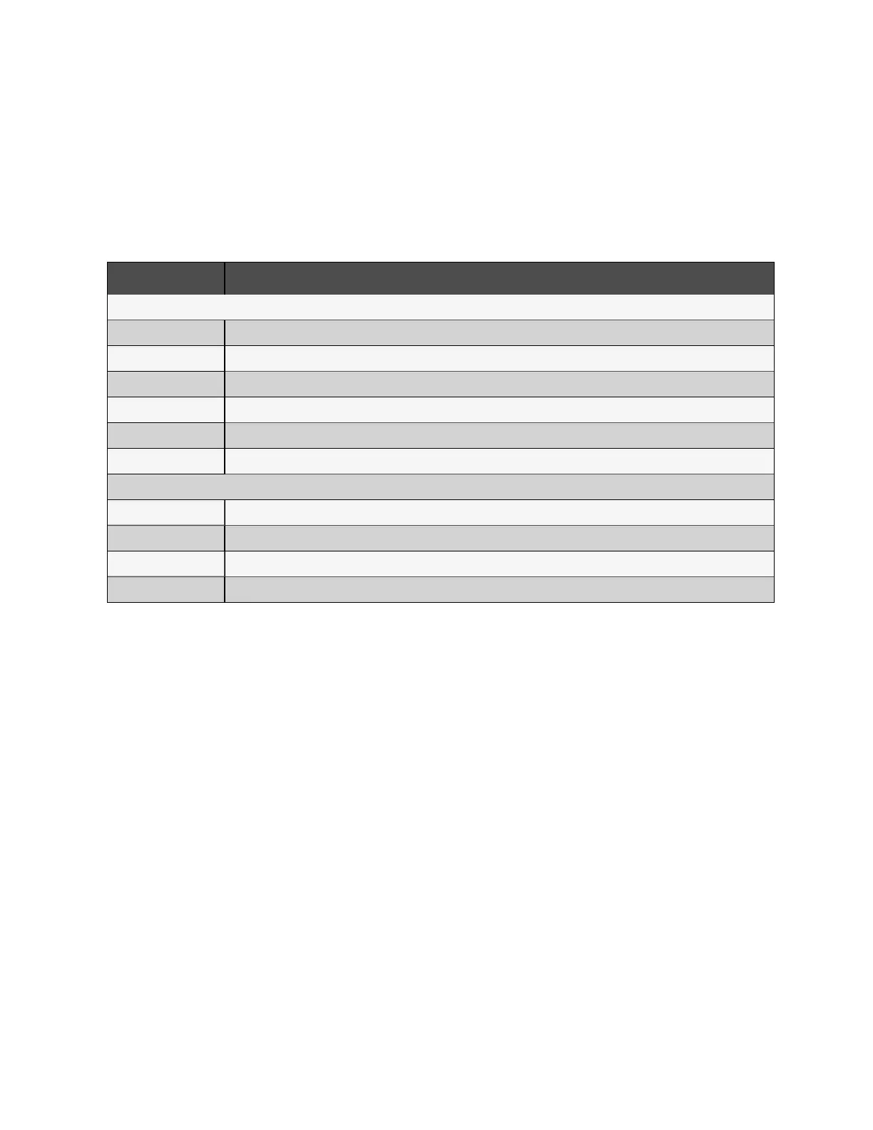
The following table lists the relevant documents by number and title.
Document Number Title
Heat Rejection Skid Dimensions
DPN003889 Cabinet and Anchor Dimensional Data Liebert® MCV330 + Liebert® EconoPhase + Base Assembly
DPN003875 Cabinet and Anchor Dimensional Data Liebert® MCV330 (2) + Liebert® EconoPhase (2) + Base Assembly
DPN004259 Cabinet and Anchor Dimensional Data Liebert® MCV440 + Liebert® EconoPhase + Base Assembly
DPN004261 Cabinet and Anchor Dimensional Data Liebert® MCV440 (2) + Liebert® EconoPhase (2) + Base Assembly
10032070 Cabinet and Anchor Dimensional Data Liebert® MCV430 + Liebert® EconoPhase + Base Assembly
10032072 Cabinet and Anchor Dimensional Data Liebert® MCV430 (2) + Liebert® EconoPhase (2) + Base Assembly
Condenser Elevation Above/Below Unit
DPN003965 Air Cooled Piping Schematic Liebert® MCV Mounted Above Liebert® DA125-D250
DPN005207 Air Cooled Piping Schematic Liebert® MCV Mounted Above Liebert® DA265
DPN005138, page 1 Air Cooled piping schematic Liebert® MCV mounted above Liebert® XDM
DPN005138, page 2 Air Cooled piping schematic Liebert® MCV mounted below Liebert® XDM
Table 3.1 Dimension Planning Drawings
10 Proprietary and Confidential ©2024 Vertiv Group Corp.
3 Pre-installation
PreparationandGuidelines
Vertiv™ Liebert® MCV Installer/User Guide