REV : A
REV DATE : 10/2023
20000040
Page :1 /1
MCV430 (2) + LIEBERT® ECONOPHASE (2) + BASE ASSEMBLY
Form No.: DPN001040_REV4
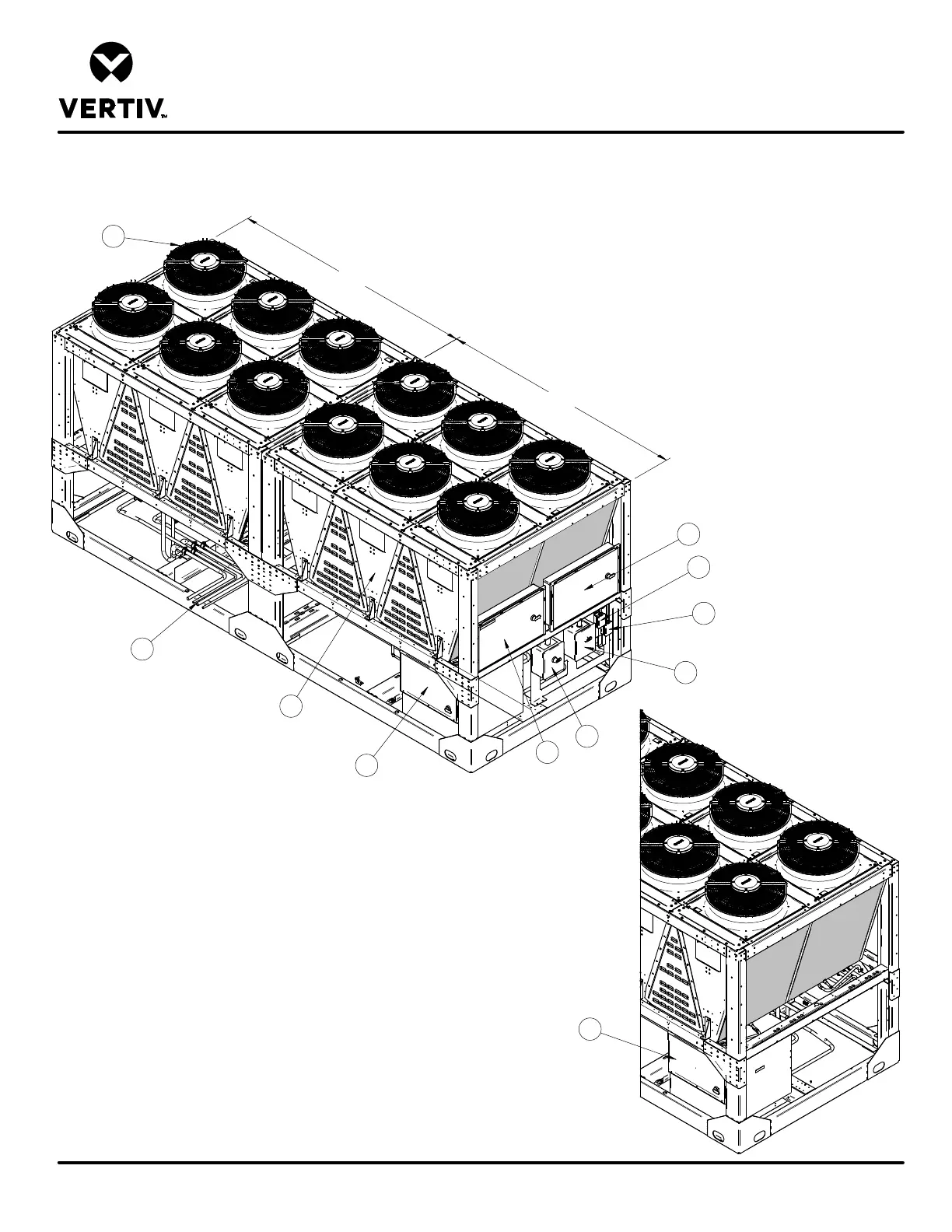
COMPONENT LOCATION DIAGRAM
HEAT REJECTION SKID
Note:
1. Piping connections for entire assembly are in one
location (item 11).
2. Electrical connections for entire assembly are located
in high voltage customer connection boxes (item 7 & 8)
and low voltage customer connection box (item 9 & 10).
Front of Unit
System 2
System 1
1. MCV430 Electric Panel System 1
2. MCV430 Electric Panel System 2
3. Coils
4. EC Fans
5. Liebert® EconoPhase System 1
6. Liebert® EconoPhase System 2
7. High Voltage Customer Connection System 1
8. High Voltage Customer Connection System 2
9. Low Voltage Customer Connection System 1
10. Low Voltage Customer Connection System 2
11. Piping Connections Systems 1 & 2
Rear of unit
6
1
2
3
4
5
7
8
9
10
11