4.5System design5
76
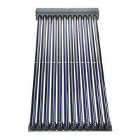
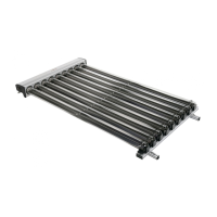
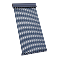
VITOSOL
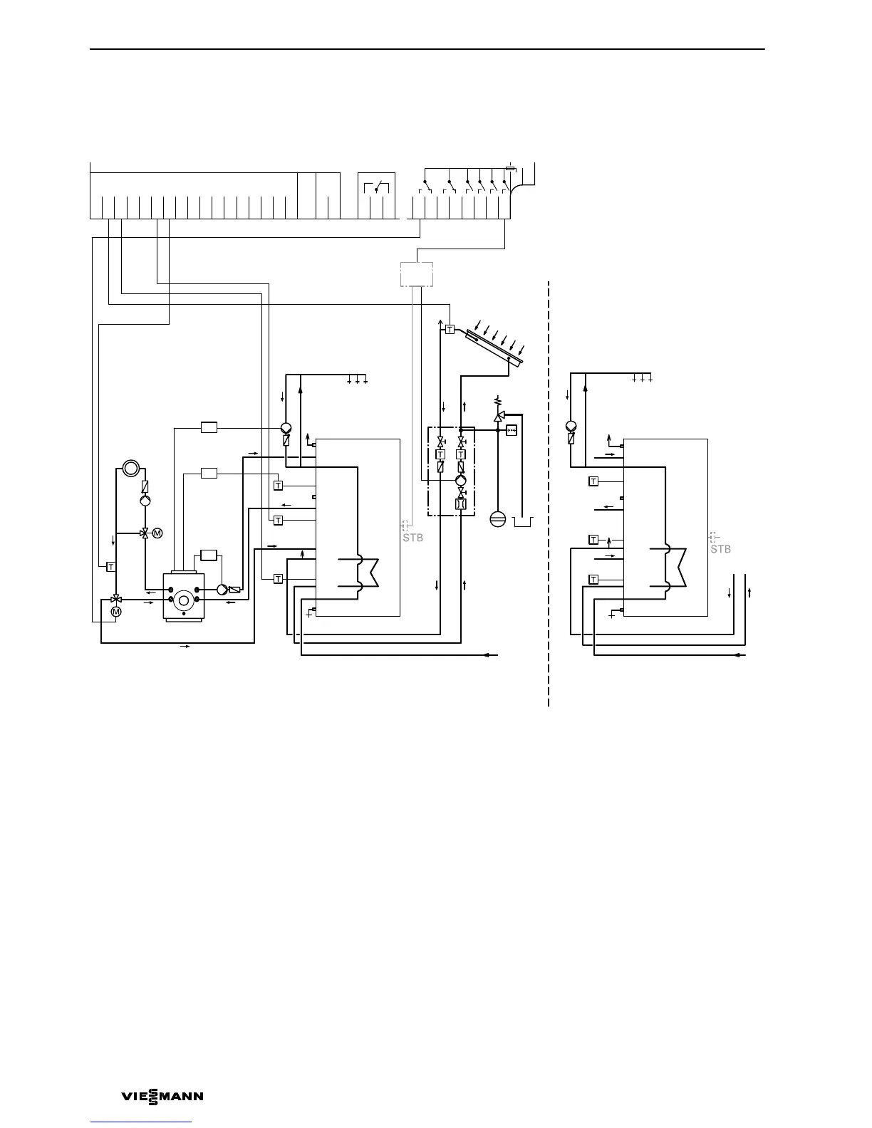
Installation diagrama
A Solar panel
B DHW circulation pump
C DHW circulation output of the boiler
control unit or on−site time switch
D Oil and gas fired boilers
E Combination cylinder Vitocell 333
or
F Heating water calorifier with
relayering system Vitocell353
G Junction box (on site)
5822135 GB
8
6
3
5
5
4
WW
AB
B
A
KW
VL RL
C
7
D
8
qP
E
B
6
3
9
A
2
28
5
21
G
GND
S1
S2
S3
S4
S5
S6
S7
S8
S9
S10
S11
S12
CS10
−−−−
Imp1
Imp2
145
145
R4
LN
R6−A
R6−R
R5−R
R5−A
R3
R2
R1
R7−A
R7−M
R7−R
1
or
WW
B
KW
VL RL
F
E
HV
HR
HV
HR
HV
HR
E
1
1
2
2
S
S
E
HV
HR
HV
HR
HV
HR
E
1
1
2
2
S
S
 Loading...