4.5System design5
77
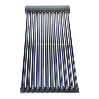
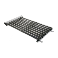
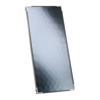
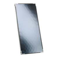
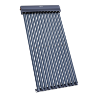
VITOSOL
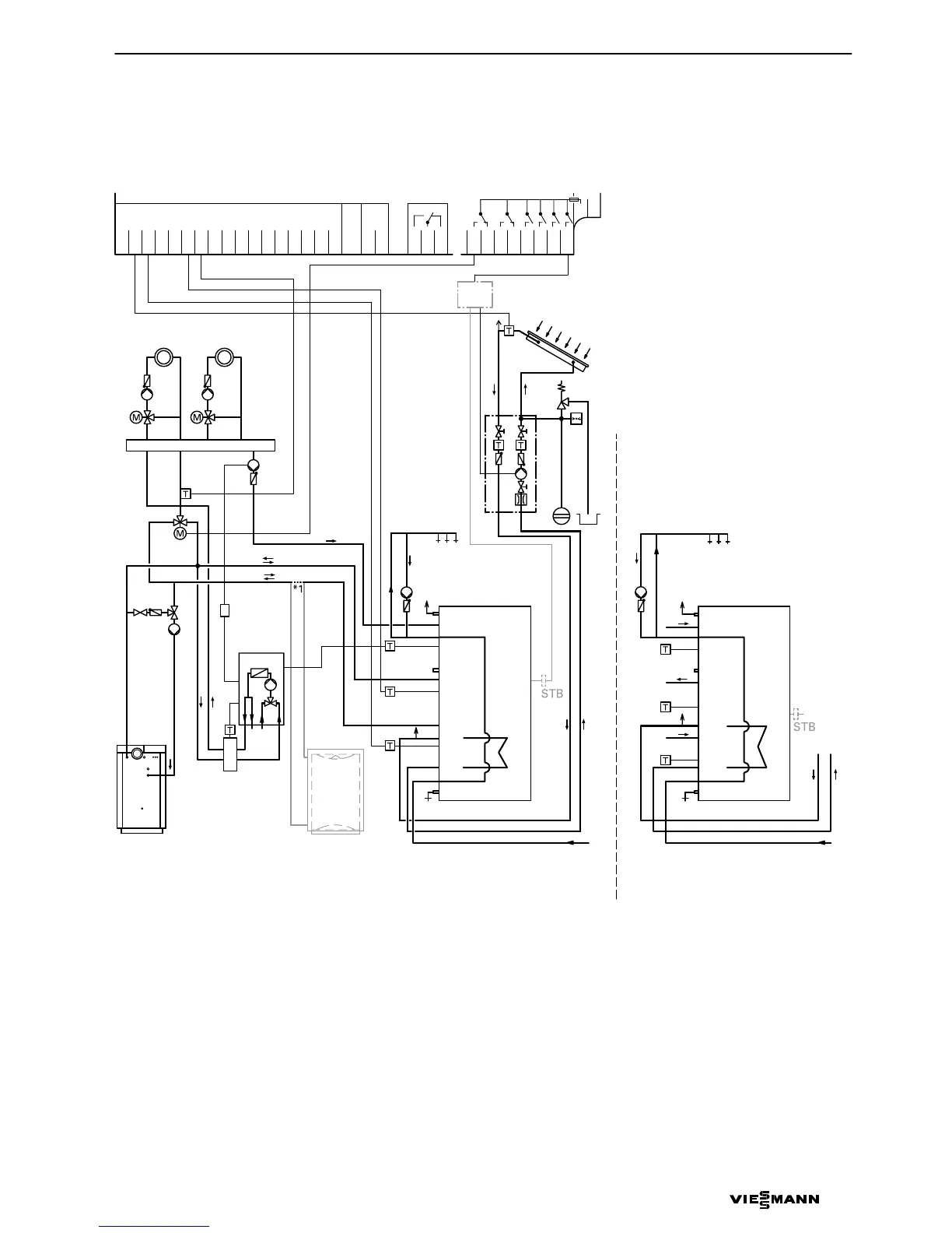
Installation diagramb
(Vitodens200 or 300, Vitopend 200, Vitoplus 300)
*1
This connection is not present when a heating water calorifier is installed.
A Solar panel
B DHW circulation pump
C Solid fuel boiler
D Boiler
E Combination cylinder Vitocell 333
or
F Stratification cylinder Vitocell353
G Vitocell 050 heating water calorifier
H Return temperature raising
K Low loss header,
part no. 7149 100
M Temperature sensor for low loss
header
H Gas fired wall mounted boilers
with Vitotronic200, type HO1,
part no.7179488
H Vitoplus300,
part no.7819601
N Junction box (on site)
5822135 GB
A
2
5
4
KW
VL RL
BA
AB
9
qP
7
8
WW
E
6
3
B
D
M
K
H
CG
N
GND
S1
S2
S3
S4
S5
S6
S7
S8
S9
S10
S11
S12
CS10
−−−−
Imp1
Imp2
145
145
R4
LN
R6−A
R6−R
R5−R
R5−A
R3
R2
R1
R7−A
R7−M
R7−R
1
qQ
8
6
3
5
or
WW
B
KW
VL RL
F
66
E
HV
HR
HV
HR
HV
HR
E
1
1
2
2
S
S
E
HV
HR
HV
HR
HV
HR
E
1
1
2
2
S
S
 Loading...